How a Gas Line Heating Jacket Maintains Precise Temperatures
A gas line heating jacket is an industrial thermal-control assembly that wraps around a process line to keep its wall temperature within a defined operating band. It is not a wearable heated garment. In gas delivery, the point is to manage heat loss along a pipe, fitting, valve, or bend so the line conditions remain consistent with the process plan.
From a thermal-management application engineer’s perspective, a gas line heating jacket should be evaluated through heat load, target temperature, gas properties, insulation, sensing, and control behavior. Looking only at heater wattage leaves important questions unanswered. A stable result depends on the whole line section and on the operating conditions around it.
Why temperature precision matters in a gas line
Many industrial gases or vapors are delivered through lines that pass through cooler ambient zones, equipment interfaces, or long routed sections. When the pipe wall loses heat faster than the system replaces it, the gas stream may see a changing thermal environment. In deposition and other tightly controlled processes, that variation can complicate repeatability. A gas line heating jacket provides distributed heat at the outside of the line while insulation reduces the rate at which that heat escapes.
Published industrial gas-line heater examples show that construction details vary substantially. One listing describes a one-piece jacket with fiberglass insulation, a coated outer layer, line sizes from 1 to 6 inches, and a stated maximum temperature of 250°C. That is an example rather than a design rule: the usable temperature range for any gas line heating jacket must be confirmed against the selected heater, line material, fittings, gas service, electrical classification, and site requirements.
The control loop behind a gas line heating jacket
A typical gas line heating jacket works as part of a closed loop. A temperature sensor measures a selected point, a controller compares that reading with a setpoint, and the controller adjusts electrical power to the heater. The jacket adds heat when measured temperature is below the control target and reduces power as the line approaches it. The response is affected by sensor location, sensor attachment, controller tuning, jacket coverage, insulation thickness, and changes in ambient conditions.
Sensor placement deserves careful attention. A sensor near a heated straight run may report a different condition from an exposed valve body or an uninsulated flange. A reading is useful only if its location represents the condition the process actually needs controlled. For a long routed section, engineers may define several control zones or use additional monitoring points rather than assuming one sensor represents the entire run.
Heat loss, coverage, and insulation work together
A gas line heating jacket does not operate in isolation. Heat leaves a line through conduction into supports and connected hardware, convection to surrounding air, and radiation from exposed surfaces. Gaps between jacket sections, uncovered elbows, poorly fitted insulation, and metal attachments can become local heat-loss paths. That means temperature control often extends beyond the jacket to pipe supports, control components, and process interfaces.
The jacket’s physical fit matters as well. A close, repeatable fit improves contact with the line and helps make heating more uniform. Removable construction can support inspection and maintenance, but it should be refitted according to the installation procedure. If heat load changes significantly, a target temperature alone is not enough to judge whether the arrangement is appropriate; the available heating capacity and control response also need review.
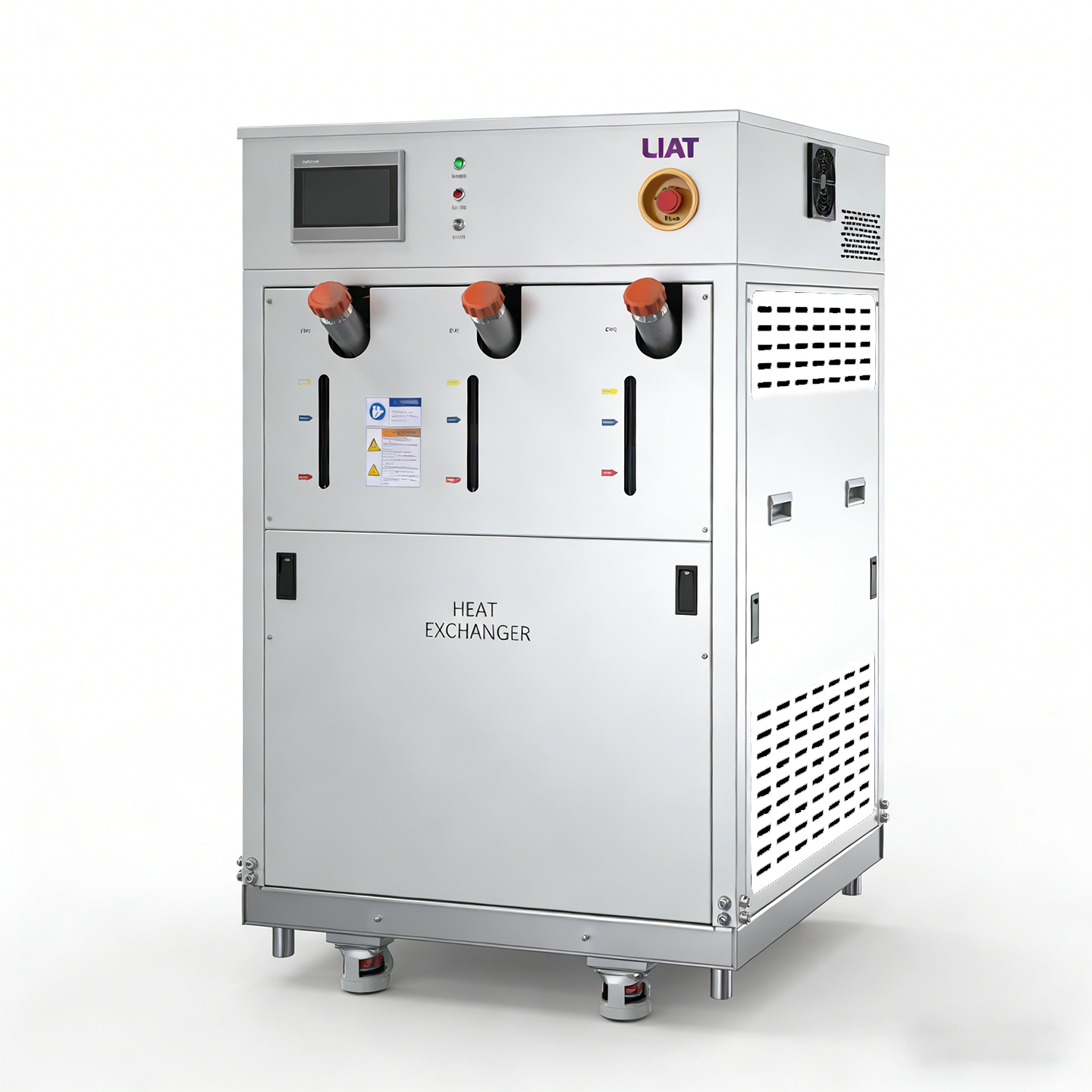
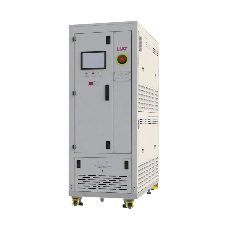 An AI-generated illustration of an industrial heated gas-line assembly.
How to specify a gas line heating jacket
Before selecting a gas line heating jacket, build a practical operating brief. Begin with the required line temperature range and the acceptable control tolerance. Then document pipe outside diameter, length, elbows, valves, flanges, material, mounting orientation, and the sections that must remain heated. Include ambient temperature, airflow, insulation condition, power supply, hazardous-area requirements where applicable, and the planned controller and sensor arrangement.
- Thermal target: Define the required temperature at the relevant process location, not just the controller setpoint.
- Physical geometry: Record diameters, bends, branch points, fittings, and access constraints so the gas line heating jacket coverage can be assessed.
- Gas and process conditions: Confirm the gas service, pressure conditions, duty cycle, and any temperature-sensitive behavior with the process owner.
- Control approach: Identify sensor locations, zoning needs, alarm limits, and what should happen after a sensor or power fault.
- Verification plan: Agree on installation checks and temperature measurements before production use.
Installation details that affect temperature stability
Even a suitable gas line heating jacket can give uneven results when installation is inconsistent. The jacket should follow the intended line geometry without stressing leads, sensors, or closures. Insulation joints should be fitted so that exposed sections are minimized, and sensor attachment should follow the approved method. Electrical connections, grounding, over-temperature protection, and access for maintenance should be reviewed by qualified personnel under the site’s safety rules.
Commissioning is where assumptions become measurable. Start at a conservative setpoint, allow the assembly to reach a stable condition, and compare readings at the control sensor with readings at the process-relevant locations. Observe startup, steady operation, and expected changes in ambient or flow conditions. If a downstream component is consistently cooler, changing the setpoint alone may not address the cause; coverage, insulation, heat sinking, and sensor position should be examined.
Maintenance and troubleshooting
Routine inspection helps keep a gas line heating jacket operating as intended. Check closures, insulation condition, lead routing, sensor attachment, controller indications, and exposed metal sections. Investigate a rising power demand, slow warm-up, unexpected temperature spread, or repeated alarms as condition signals rather than simply resetting the controller.
A practical troubleshooting sequence starts by confirming the measured temperature, then checking the sensor position, supply power, controller output, jacket coverage, and heat-loss paths at fittings and supports. This problem-cause-solution approach keeps the discussion tied to evidence. It also avoids making a broad claim about the jacket when the issue may be a process connection or an incomplete installation.
Turn a target temperature into a verified operating condition
A gas line heating jacket maintains precise temperatures by combining controlled electrical heat with suitable coverage, insulation, sensing, and commissioning. The practical question is not whether a jacket can add heat; it is whether the installed system can hold the required condition at the location that matters to the process. By defining the operating window, mapping heat-loss points, and verifying temperatures after installation, teams can make a more defensible engineering decision for each line section.
 Hot News