
How to Design a Pipe Heating System for Long Delivery Paths
A long delivery path changes the design problem. A short branch can sometimes tolerate a little thermal uncertainty; a long line cannot. Heat is lost continuously through insulation, supports, valves, and exposed sections, while voltage drop, circuit length, and control response become more consequential as distance increases. From a thermal-management application engineer’s perspective, a reliable pipe heating system begins with the process condition rather than the heater selection.
This guide outlines a practical way to design a pipe heating system for temperature maintenance or freeze protection over long runs. It applies to electric tracing concepts, including a pipe heater jacket or pipe heating jacket where a removable external heating solution suits the asset. The final design still needs a project-specific calculation, electrical review, and installation verification.
Start with the duty, not the cable
Before comparing heater types, define what the line must achieve. Is the objective to prevent freezing, prevent viscosity from rising, maintain a process temperature, or recover temperature after an interruption? These duties lead to different setpoints, allowable temperature bands, and startup expectations. A pipe heating system that merely offsets steady heat loss may not have enough margin to warm a cold, stagnant line within the required time.
Create a line schedule that divides the route into meaningful sections. For each section, record pipe material, nominal size, actual route length, fluid or product condition, minimum ambient temperature, wind or exposure condition, insulation type and thickness, fittings, valves, instruments, supports, and available power. If the route crosses indoor and outdoor areas, treat them as separate thermal zones. The same nominal pipe can need different heat input when its surroundings change.
Calculate heat loss by segment
At a conceptual level, steady heat loss increases with surface area and the temperature difference between the pipe contents and the surroundings. A relationship often expressed as Q = U × A × ΔT is useful for understanding the direction of the result, but it is not a complete tracing design. The overall heat-transfer coefficient depends on insulation, geometry, surface condition, and the external environment. A long pipe heating system should therefore use a documented segment calculation rather than one average watt-per-metre value for the full route.
Use the coldest credible design condition for normal temperature maintenance, then test the resulting load against the intended heater output at the actual supply voltage. Account separately for known thermal bridges: valves, flanges, pumps, strainers, supports, instrument connections, and uninsulated maintenance clearances. These items do not behave like a plain insulated pipe metre. Where the calculation calls for extra heat at an accessory, show the allowance on the isometric or installation drawing so it is not lost during construction.
Choose the heating method around access and geometry
For a fixed, long route, distributed electric trace heating is often evaluated because heat can follow the pipe over its length. The selection must consider the required maintained temperature, maximum exposure temperature, chemical environment, hazardous-area requirements where applicable, and the available circuit arrangement. Do not assume one heater family is universally suitable; the product data and local electrical rules set the actual limits.
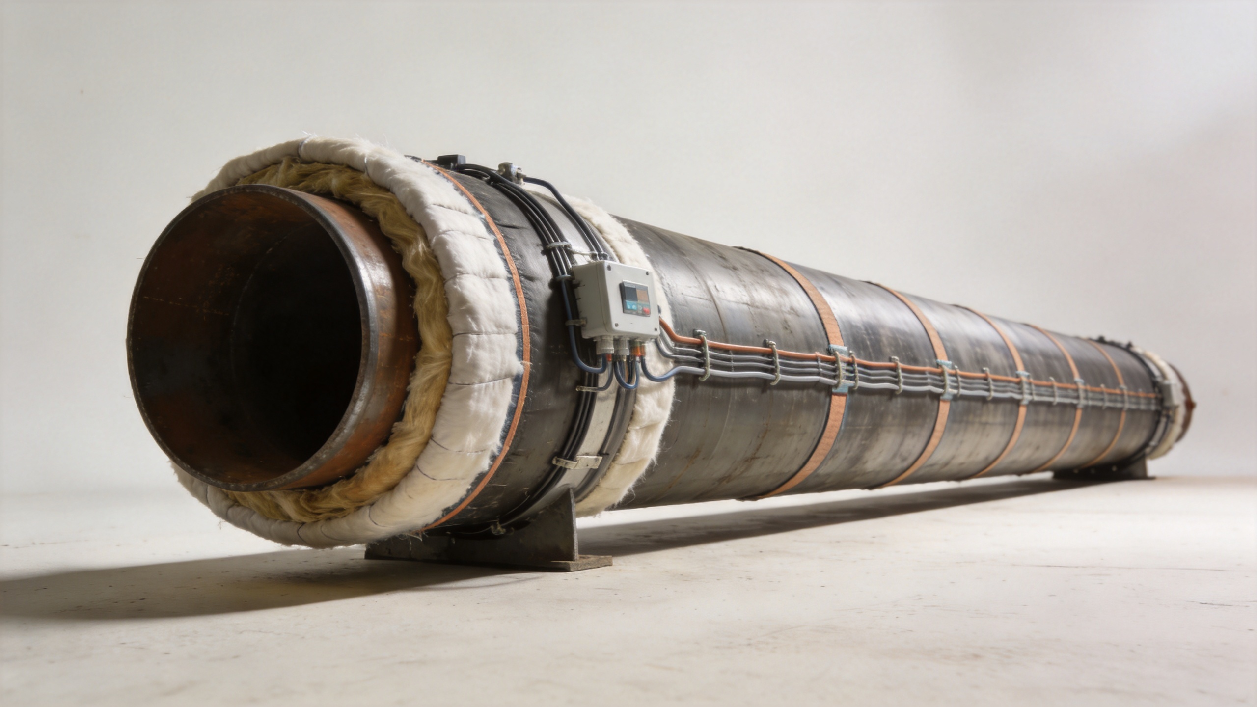
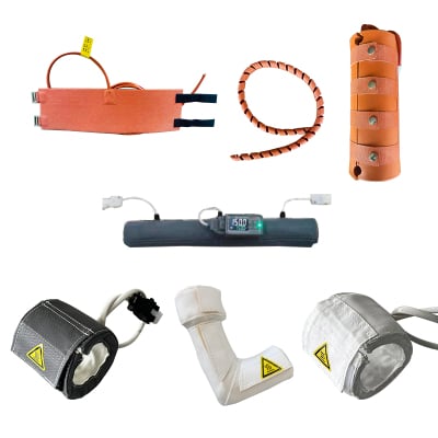
A pipe heater jacket can be useful on short, irregular, or frequently accessed sections such as valves, filters, elbows, or removable equipment. A pipe heating jacket may simplify maintenance because it can be removed and reinstalled, but its closure, contact quality, insulation interface, and lead routing still need design attention. For a long delivery path, it is often better to use jackets selectively at difficult components rather than treating them as a substitute for a route-wide heat-loss plan.
Break a long route into electrical and control zones
Long delivery paths should rarely be designed as one undifferentiated circuit. Divide the pipe heating system at logical points: changes in ambient exposure, pipe diameter, process duty, insulation, route direction, or maintenance boundary. Zoning makes it easier to keep circuit length within the heater manufacturer’s limits, manage voltage drop, isolate a fault, and tune control to the local duty.
For every zone, document the calculated load, heater length, nominal power, protective device, controller or thermostat, sensor location, junction boxes, and end termination. Put temperature sensors where they represent the worst thermal condition rather than where installation is easiest. A sensor mounted near a warm indoor penetration can give a misleadingly comfortable reading for a cold outdoor reach. If the process is sensitive, consider whether temperature monitoring alone is enough or whether power monitoring and alarm logic are also needed.
Design the insulation and weather barrier as part of the system
Heaters replace heat that escapes; insulation reduces the heat that must be replaced. Poorly fitted insulation, wet insulation, crushed sections, or unsealed cladding can undermine an otherwise sound pipe heating system. Specify compatible insulation, vapour or weather protection where needed, and a repair method for locations opened during maintenance. The heater, insulation, cladding, and support detail should be reviewed together.
Pay attention to penetrations and transitions. Cable entries, instrument tees, pipe supports, and equipment nozzles create places where both heat loss and installation errors can concentrate. A clear detail for each recurring condition is more valuable than a generic note saying “provide extra heat as required.”
Plan installation, testing, and commissioning early
Installation quality determines whether the calculated performance reaches the pipe. Verify that the heater is attached in the intended position, does not cross itself unless specifically permitted, has protected terminations, and remains accessible for inspection where required. Confirm insulation is installed after the heating circuit has passed the required electrical checks.
Commission by comparing the design intent with measured results. Record insulation-resistance and continuity checks according to the approved procedure, confirm controller setpoints and alarms, and observe temperature behaviour at representative cold locations. If a zone underperforms, separate the diagnosis: confirm actual supply voltage and heater output, inspect insulation and exposure, then review sensor placement and the heat-loss assumptions. Replacing a controller will not correct an underestimated outdoor load.
A final design checklist
- Define the process temperature objective and cold-start expectation.
- Calculate heat loss by environmental and construction segment.
- Include fittings, valves, supports, and exposed equipment in the heat budget.
- Check heater output, circuit length, voltage drop, and protection for each zone.
- Use a pipe heater jacket or heating jacket where removable local coverage is genuinely advantageous.
- Coordinate heater routing with insulation, cladding, drainage, access, and maintenance needs.
- Verify performance during commissioning at the locations most likely to lose heat.
The strongest long-run design is not the one with the highest nominal wattage. It is the one that connects a documented heat-loss model to practical zoning, installation details, controls, and field verification. That approach gives the pipe heating system a clearer operating margin and gives the project team a traceable basis for refining it when real site conditions differ from the original assumptions.
 Hot News