
How a Pipe Heating System Prevents Condensation in Gas Delivery Lines
Condensation in a gas delivery line is rarely solved by adding heat without first defining the condition that creates the moisture. From a thermal-management application engineer’s perspective, a pipe heating system works when it keeps the relevant pipe surface and gas path above the applicable dew-point condition while responding to heat loss, flow changes, and control limits. That sounds simple, but the useful design question is not “how hot should the line be?” It is “which temperature, under which operating condition, must remain above which dew point?”
A well-matched pipe heating system can help reduce liquid formation, protect downstream instruments, and make gas service more stable. It is not a substitute for drying, filtration, pressure management, or a process safety review. The right approach is to establish the moisture source, calculate or confirm the design conditions, and then verify the installed system under realistic ambient and operating changes.
Why condensation forms in gas delivery lines
Gas can carry water vapor even when the line initially appears dry. If the gas cools, if a pipe wall is colder than the gas, or if ambient conditions drive a local cold spot, vapor can reach saturation and form liquid. Pressure changes can also change the dew-point relationship. In a delivery system, the practical consequence may be droplets, unstable analyzer readings, corrosion risk, freeze-up in cold areas, or contamination at a point of use.
The key distinction is between gas temperature and pipe-surface temperature. A warm bulk-gas reading does not prove that every fitting, valve body, support, or exposed branch is warm enough. A pipe heating system is therefore a heat-loss control strategy, not merely a cable wrapped around a straight run. The design must account for the coldest credible location and the worst credible operating condition.
How a pipe heating system changes the condensation balance
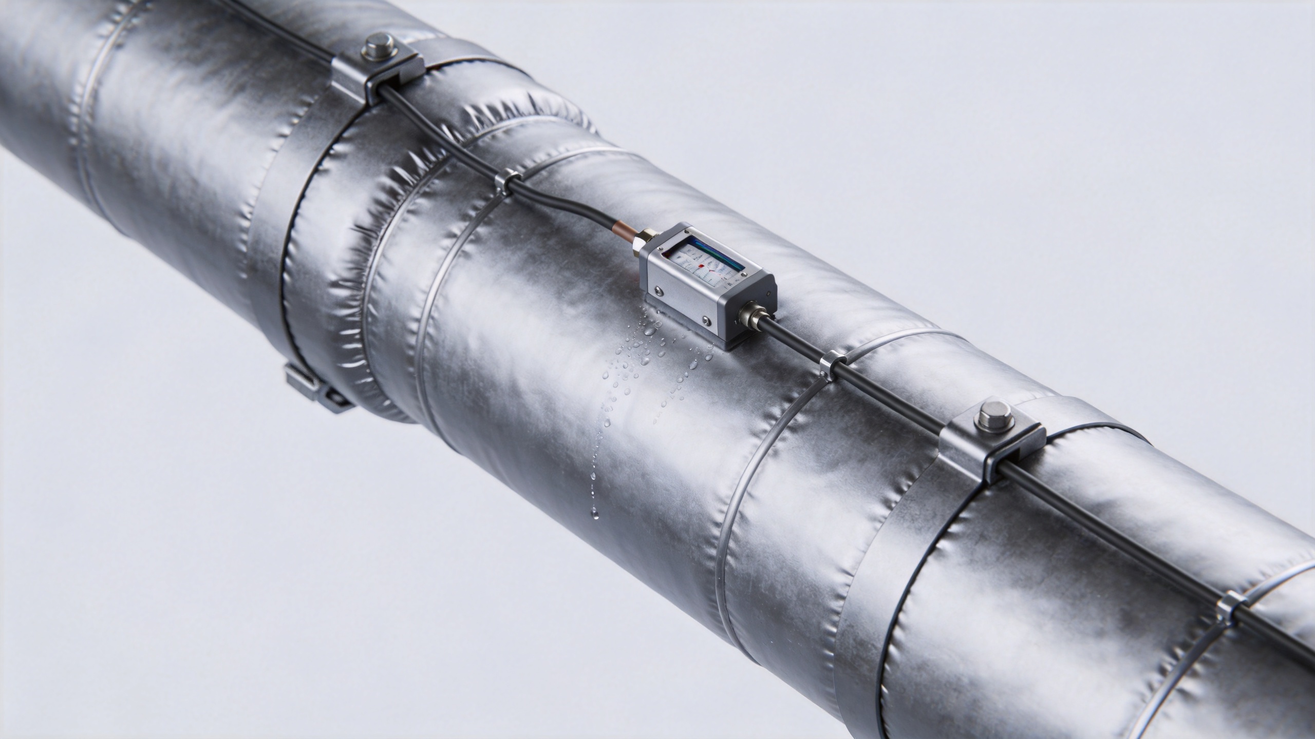
A pipe heating system supplies controlled heat to offset heat leaving the line. With appropriate insulation, the system can keep the pipe wall in a planned temperature band instead of allowing it to track a cold room, outdoor air, washdown exposure, or a low-flow period. The goal is to preserve a usable margin above the confirmed dew point, rather than to drive the line to an unnecessarily high temperature.
This is why a pipe heating jacket or a flexible heating jacket can be useful on irregular sections. Flanges, regulators, small vessels, elbows, and instrument connections often lose heat differently from a straight pipe. A removable heating jacket may help cover a geometry that is difficult to trace uniformly. However, it still needs suitable contact, temperature sensing, insulation strategy, and safe electrical design. A jacket alone cannot establish that a system has adequate heat input.
Start with the conditions that set the required temperature
Before specifying a pipe heating system, collect the operating information that governs condensation risk:
- Gas composition, moisture specification, pressure, and expected dew point.
- Normal, startup, shutdown, and low-flow temperatures.
- Lowest credible ambient temperature, air movement, weather exposure, and washdown conditions.
- Pipe material, diameter, length, fittings, supports, valves, and uninsulated interruptions.
- Available power, control architecture, area classification, maintenance access, and alarm expectations.
These inputs clarify whether the issue is external surface condensation, condensation inside the gas path, or both. If only a target temperature is known but the moisture condition and heat loss are not, it is too early to compare a pipe heater jacket, self-regulating trace, or another heating approach. The required margin depends on the complete condition set.
Heat input, insulation, and coverage work together
A pipe heating system is typically evaluated as a combination of heater output, thermal contact, insulation, and control. The heater replaces heat lost to the environment. Insulation reduces that loss and helps smooth temperature variation along the line. If insulation is wet, damaged, compressed, or interrupted at supports and fittings, the heat balance can change significantly. For this reason, insulation inspection belongs in the condensation-prevention plan rather than being treated as a cosmetic detail.
Coverage also matters. Straight-line wattage may be adequate on paper while a metal valve, a large flange, or an exposed support remains a cold spot. In those locations, a heating jacket can provide more practical coverage than a straight tracing layout. Conversely, a pipe heating jacket should not be selected only for convenience; its temperature rating, fastening method, removable insulation arrangement, and compatibility with the equipment geometry need verification.
Control the coldest meaningful point, not just the easiest point to measure
Control design determines whether a pipe heating system maintains a useful dew-point margin over time. A sensor placed near a warm heater zone may report a reassuring temperature while an upstream fitting is colder. Sensor location should reflect the likely limiting point, and the control setpoint should be documented against the confirmed dew point and expected measurement uncertainty.
Depending on the application, the system may use a thermostat, a surface sensor with a controller, or a more integrated monitoring approach. The right choice depends on the required temperature band, the consequence of deviation, and the maintenance model. It is also sensible to define high-temperature limits and fault response. More heat is not automatically safer or more effective; excessive temperature can create material, process, or area-classification concerns.
Where heating jackets fit in a gas-line design
A heating jacket is often a practical part of a broader pipe heating system when the line includes removable components or irregular thermal masses. Common candidates include regulators, sampling assemblies, filters, valve clusters, and small manifolds. A pipe heater jacket can simplify access for inspection or replacement, but it must not obscure leak checks, labels, emergency isolation, or required service access.
For a gas line in a classified or otherwise controlled area, electrical equipment selection and installation practices must be reviewed against the applicable site requirements. This is a design and safety verification task, not a claim that any particular heating jacket or cable is suitable. Confirm enclosure ratings, cable routing, grounding, overtemperature protection, and inspection procedures with qualified personnel.
A practical verification sequence
- Confirm the moisture condition and determine the dew point for the intended pressure and gas composition.
- Identify the coldest sections, including fittings, dead legs, supports, and low-flow zones.
- Define the required temperature margin and calculate heat loss for the design ambient condition.
- Select the pipe heating system layout, including trace or jacket coverage, insulation, sensors, controls, and safety limits.
- Inspect the installed line for gaps, poor thermal contact, wet insulation, unsupported sections, and inaccessible maintenance points.
- Commission the system through normal and adverse operating conditions, then record surface temperatures and any condensation observations.
Conclusion: prevent condensation by maintaining a verified margin
A pipe heating system prevents condensation when it is engineered as part of the full thermal boundary: gas condition, pipe surface, ambient exposure, insulation, coverage, sensing, and control. A pipe heating jacket or pipe heater jacket can be valuable for difficult components, but it should support a documented heat-loss and dew-point strategy rather than replace one. The most reliable next step is to assemble the operating data, identify the coldest credible point, and validate the installed temperature margin under the conditions that matter to the process.
 Hot News