
How Does an Industrial Chiller Work Step by Step
When a process drifts outside its temperature window, the problem is rarely solved by simply “making cold.” The useful question is: how does an industrial chiller work as part of a complete thermal loop? An industrial chiller removes heat from a circulating process fluid, carries that heat through a refrigeration circuit, and releases it at the condenser. The cooled fluid then returns to equipment such as a reactor jacket, laser, test fixture, battery system, or semiconductor tool.
From a thermal-management perspective, stable results depend on the entire path: heat load, fluid flow, piping, control logic, and heat rejection. The step-by-step sequence below separates the process-fluid loop from the refrigerant loop, which makes troubleshooting much more practical.
Start with the two loops inside an industrial chiller system
An industrial chiller usually has two connected but separate circuits. In the process loop, water or another approved heat-transfer fluid travels between the chiller and the machine. It absorbs unwanted heat at the load and returns warmer. In the refrigeration loop, refrigerant changes pressure and state to move that collected heat to the condenser. A heat exchanger transfers energy between the loops without mixing their fluids.
This distinction matters during diagnosis. A warm supply temperature can come from insufficient process flow, a dirty heat-transfer surface, a high condenser temperature, a control setting, or a refrigeration-side fault. Treating every temperature issue as a compressor issue skips several likely checks.
Step 1: The process puts heat into the circulating fluid
The cycle begins at the application. Motors, electronics, reactions, tools, or friction add heat to the process. A pump carries the return fluid back toward the chiller. At this point, the temperature difference between the supply and return lines is useful information, but it should be interpreted with the actual flow rate and load condition. A small temperature difference does not automatically mean low heat load; high flow can produce the same observation.
Before selecting or operating a system, define the expected heat load, required supply-temperature range, fluid type, flow range, allowable pressure drop, ambient condition, and control connection. These inputs establish whether the chiller has a workable operating margin.
Step 2: The evaporator absorbs heat from that fluid
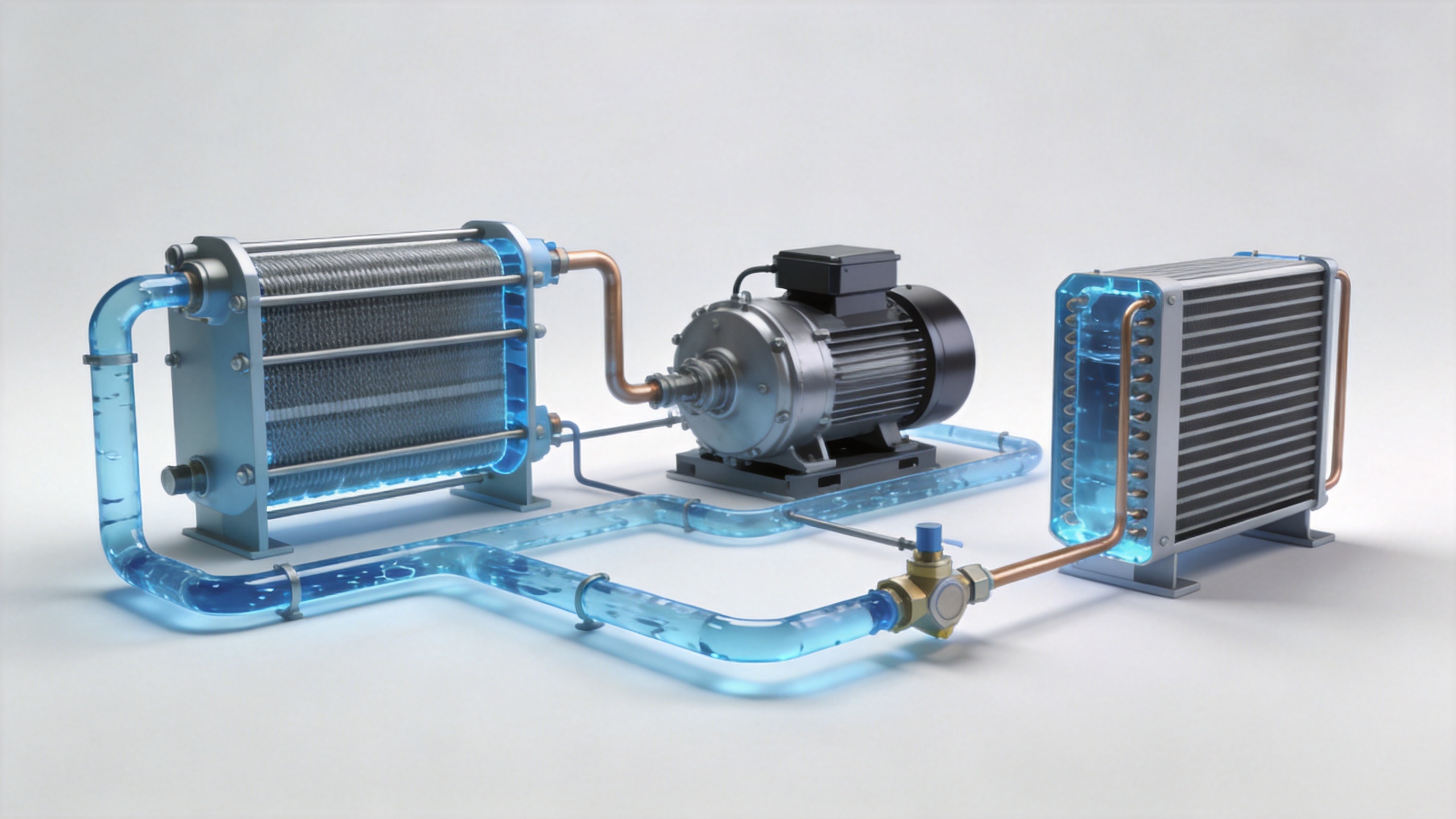
Inside the evaporator, the warmer process fluid passes across one side of a heat exchanger. Low-pressure refrigerant passes through the other side. Because the refrigerant is at a lower saturation temperature, it absorbs heat and evaporates. The process fluid leaves cooler and is sent back to the equipment.
Evaporator performance depends on clean heat-transfer surfaces and adequate, steady flow. A blocked strainer, trapped air, unsuitable fluid mixture, or pump issue can reduce heat transfer even when the refrigeration circuit is operating. For this reason, an industrial chiller controller commonly monitors supply temperature, return temperature, flow or flow proof, and protection conditions.
Step 3: The compressor raises refrigerant pressure and temperature
The vapor leaving the evaporator enters the compressor. Compression raises its pressure and temperature so the refrigerant can reject heat at the condenser. This is the energy-input step of a common vapor-compression cycle.
Compressor operation is controlled rather than treated as a simple on/off event. Depending on the design, the controller may stage capacity, modulate speed, or use unloading logic in response to temperature demand and operating limits. The objective is to match cooling capacity to a changing load while keeping suction, discharge, and motor conditions within the equipment’s approved range.
Step 4: The condenser releases heat to air or water
At the condenser, the hot high-pressure refrigerant gives up heat and changes back toward a liquid state. This is where the heat removed from the process ultimately leaves the system.
An air-cooled industrial chiller uses fans and a finned coil to transfer heat to surrounding air. It is often selected where a cooling-water system is unavailable, but its performance is closely tied to ambient temperature, airflow, coil cleanliness, and installation clearance. A water-cooled arrangement transfers heat to a separate condenser-water loop, often connected to an external heat-rejection device. That arrangement adds water-side equipment and maintenance considerations, including flow, water quality, and material compatibility.
Step 5: The expansion device lowers pressure before the next pass
After condensing, liquid refrigerant reaches an expansion device. The device meters refrigerant into the low-pressure side of the cycle. Its pressure drops, its temperature falls, and it enters the evaporator ready to absorb heat again. The cycle then repeats continuously while the process needs cooling.
The expansion device works with the evaporator, compressor, and controller as a system. If refrigerant feed is not matched to load and heat-transfer conditions, the chiller may have unstable temperatures or protective shutdowns. Diagnosis should therefore look at measured operating conditions and the manufacturer’s service procedure rather than changing settings by guesswork.
Step 6: The process-fluid pump sends cooled fluid back to the load
Once heat has been removed in the evaporator, the pump circulates cooled fluid to the process again. The chiller is not isolated from the machine it serves: pipe length, elevation, hose size, valve position, bypass paths, and the machine’s own heat exchanger all influence delivered temperature and stability.
For precise work, confirm that the temperature sensor location represents the process requirement. A supply sensor near the chiller may not reflect the temperature at a distant tool after heat gain in the line. Similarly, the process may need a controlled ramp rather than an abrupt setpoint change. Ask what temperature is required, where it is measured, and how quickly it may change.
What the controller and safety devices do during operation
A modern industrial chiller coordinates pumps, compressors, fans or condenser-water equipment, valves, and alarms. It compares measured temperatures with the setpoint and responds to valid demand. Protective logic can stop or limit operation when it detects conditions such as poor flow, high pressure, low pressure, overtemperature, sensor faults, or electrical abnormalities.
These protections are not merely nuisance alarms. They are clues about where the thermal path may be restricted. For example, high condensing pressure points attention toward heat rejection and airflow or water flow; a flow-related alarm points first toward the process loop. Exact alarm meanings and reset procedures vary by model, so use the equipment documentation for service decisions.
A practical startup and maintenance checklist
- Confirm the process fluid and concentration are compatible with the approved operating range.
- Verify fill level, vent trapped air, inspect hoses and fittings, and confirm valves are in the intended position.
- Check that process flow is present before expecting stable cooling.
- Keep air-cooled condenser surfaces and clearances clean; verify water-side flow and water-treatment practice where applicable.
- Trend supply temperature, return temperature, pressure indications, alarm history, and changes in process load.
- Have qualified personnel inspect the sealed refrigerant circuit and follow applicable handling requirements.
Putting the cycle into an application context
So, how does an industrial chiller work in daily production? It repeatedly removes heat from a controlled process: the fluid collects heat, the evaporator transfers it to refrigerant, the compressor raises the refrigerant’s pressure, the condenser rejects the heat, and the expansion device prepares refrigerant for another pass. The system performs well when the chiller, piping, process load, controls, and heat-rejection side are considered together.
For a new project or a recurring temperature issue, start with the operating conditions rather than a single nameplate number. A clear record of temperature range, heat load, fluid, flow, ambient conditions, connections, and maintenance capability gives engineering teams a sound basis for evaluating an industrial chiller configuration.
 Hot News