
How a Battery Thermal Testing System Maps Temperature Effects
When a battery program needs to understand temperature behavior, a single chamber setpoint is not enough. A battery thermal testing system helps engineers create a controlled temperature history, synchronize it with electrical loading, and capture where and when the test article warms or cools. The useful outcome is not merely a pass/fail record. It is a temperature-effect map that shows how ambient conditions, current demand, sensor location, and thermal paths interact.
From a thermal-management application engineer’s perspective, the first question is usually not “Which unit should we buy?” It is “What temperature effect are we trying to separate?” A cell surface, a tab region, a module center, and a coolant contact point can respond on different time scales. A well-planned battery thermal testing system makes those differences visible without turning every change in temperature into a vague conclusion.
What a temperature-effect map actually shows
A temperature-effect map is an organized comparison of measured temperatures and operating signals across defined conditions. The horizontal axis might be time, state of charge, discharge rate, or a programmed temperature step. The vertical axis may show sensor position, test sequence, or operating condition. Color or separate traces then reveal temperature change, temperature spread, stabilization time, or a lag between the environmental condition and the battery response.
The map becomes more useful when it connects four evidence streams:
- Boundary condition: the commanded air, liquid, plate, or fixture temperature.
- Battery response: temperatures at documented positions on the cell, module, or pack.
- Electrical context: current, voltage, state of charge, and the timing of charge, discharge, or rest periods.
- Test-system behavior: actual temperature, ramp behavior, flow where applicable, alarms, and any control deviation.
A battery thermal testing system can establish a repeatable boundary condition, but interpretation also depends on sensor contact, fixture pressure, heat rejection, wiring, and the electrical plan.
Start with the question before setting the temperature profile
Different questions call for different maps. For example, an engineering team may want to compare low-temperature power behavior, observe heat accumulation during repeated pulses, check temperature uniformity across a module, or verify recovery after a high-load event. Each question changes the useful temperature range, dwell period, sampling rate, and sensor layout.
For reliability work, the applicable test standard and product specification should define the required conditions. IEC 62660-2:2018 covers reliability and abuse test procedures for secondary lithium-ion cells and cell blocks used in road vehicles. Secondary-source descriptions of that standard mention temperature cycling between −40 °C and +85 °C as an example condition. It should be treated as context rather than a universal recipe: the correct limits, cycle count, instrumentation, and acceptance criteria depend on the relevant standard and the validation plan.
Before configuring a battery thermal testing system, write down the expected decision at the end of the test. Examples include:
- Identify the temperature range where electrical performance changes enough to require a control strategy.
- Compare thermal gradients between two fixture or cooling concepts.
- Determine whether the temperature response has stabilized before an electrical measurement is taken.
- Locate positions that need additional sensing in later validation work.
Build the test loop around control, measurement, and correlation
1. Define the thermal boundary
The thermal boundary may come from chamber air, a liquid plate, a conditioned fixture, or an industrial chiller connected to a controlled loop. The method should match the test article and the heat path being studied. Air conditioning is useful when the objective is environmental exposure; a liquid loop or plate may be more relevant when the battery is designed to exchange heat through a coolant contact surface.
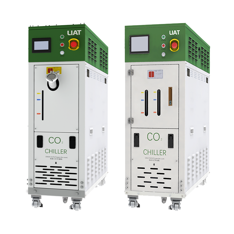
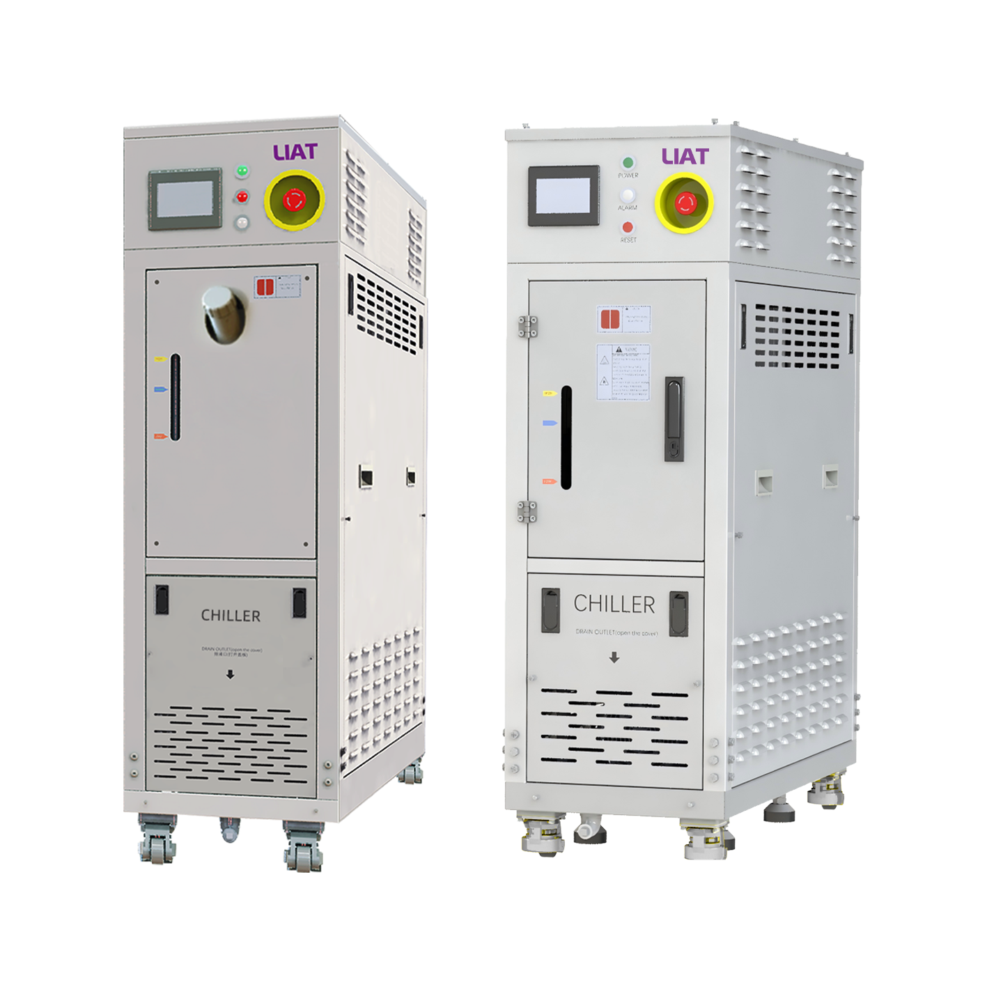
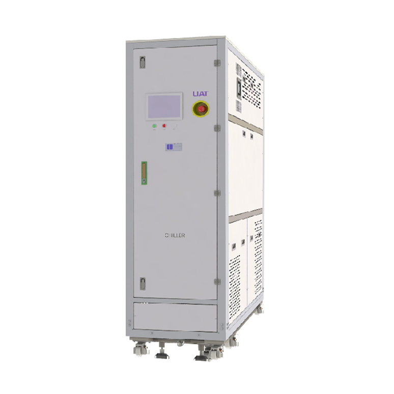
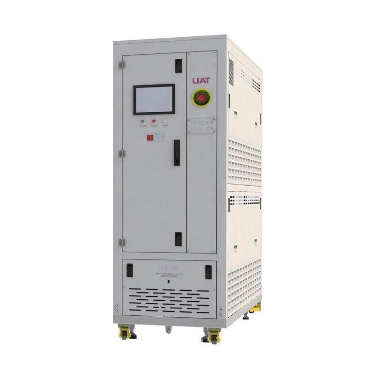
For an industrial chiller setup, document the circulating medium, target temperature, nominal flow, connection points, insulation approach, and the points at which supply and return temperatures are measured. A stable controller display alone is not enough. The test record should show whether the battery contact surface experienced the intended condition and the heat removed by the loop during the event.
2. Place sensors to answer a physical question
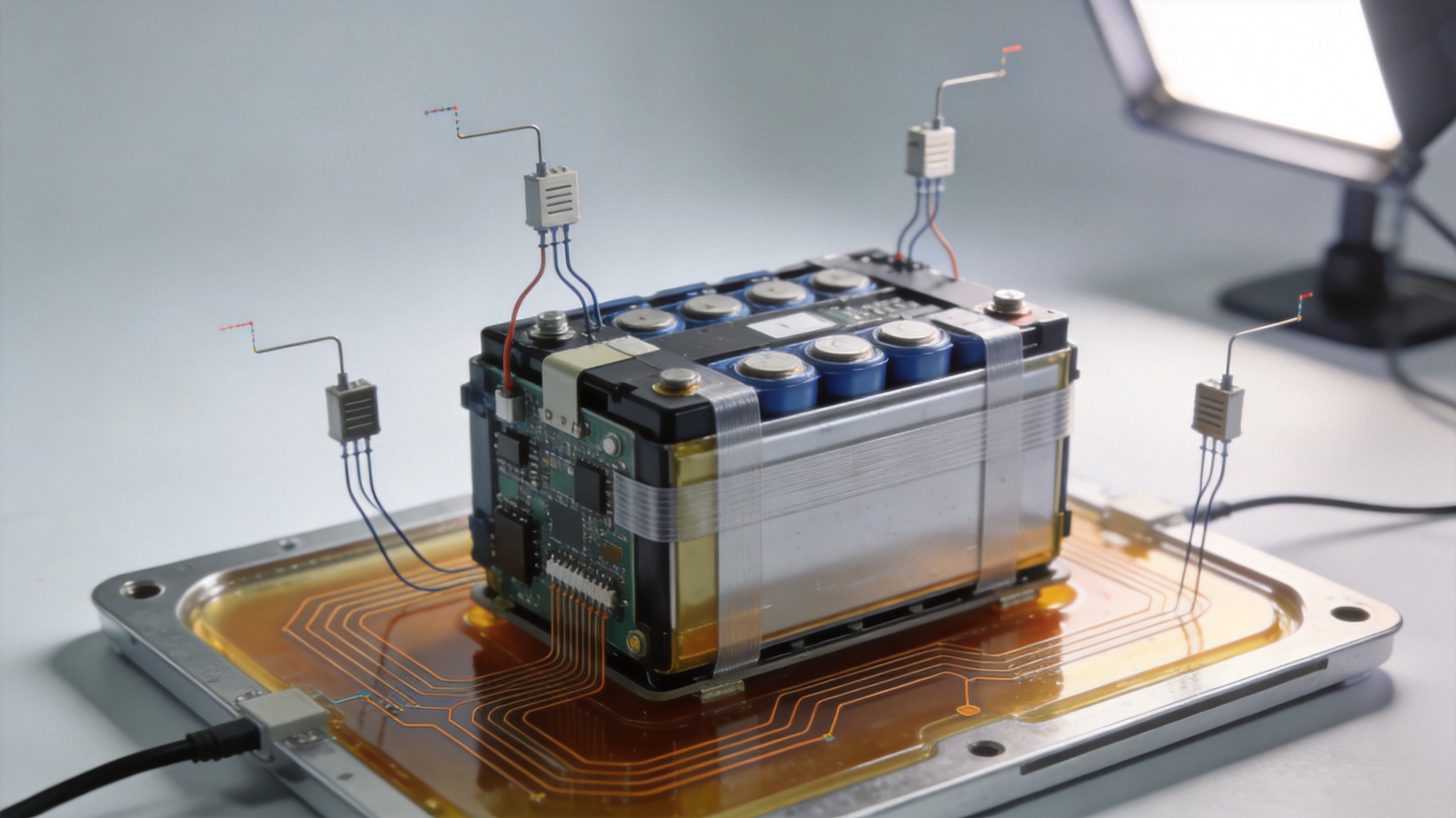
Sensor count is less important than sensor purpose. Place sensors where heat is likely to enter, leave, or concentrate: representative cell surfaces, tabs, busbar regions, module centers, coolant inlet and outlet locations, and the fixture itself. Use a repeatable attachment method and record it. Published measurement discussions also note that placement, response delay, and electrical-isolation constraints can affect what a temperature trace means.
One external sensor can be useful for protection, but it cannot define a full temperature-effect map. If a peak occurs in one region before another sensor responds, the delay may reflect thermal propagation, sensor mounting, or both. A battery thermal testing system should therefore capture enough context to distinguish these possibilities.
3. Synchronize thermal and electrical data
Align temperature values with current, voltage, and state of charge. Mark ramps, pulses, rests, and protection limits so the map can be reviewed against operating events.
Use a staged profile instead of one dramatic excursion
A practical battery thermal testing system often uses stages: condition the article, hold until a defined stability criterion is met, apply an electrical event, observe the response, and recover before the next condition. This approach isolates cause and effect more clearly than immediately moving from one extreme to another.
| Stage | What to record | Why it matters |
|---|---|---|
| Preconditioning | Initial temperature, state of charge, sensor agreement | Creates a comparable starting point. |
| Temperature ramp | Commanded and measured boundary temperatures, ramp timing | Shows whether the test article tracks the intended condition. |
| Dwell | Temperature spread, stabilization trend, controller deviation | Confirms whether an electrical measurement is being taken under a defined condition. |
| Electrical event | Current, voltage, sensor traces, coolant or air response | Relates heat generation to operating demand. |
| Recovery | Cooling or warming rate, residual gradient, alarms | Reveals thermal inertia and readiness for the next stage. |
Set the dwell criterion in the engineering plan before reviewing the result. It may be a maximum difference across selected sensors or a defined rate of temperature change.
Turn raw traces into a useful map
After the run, organize data by comparable condition rather than by file name. For every programmed condition, calculate or visualize the measured boundary temperature, peak battery temperature, maximum sensor-to-sensor spread, time to stabilization, and the time offset between electrical loading and the thermal peak. These measures make it easier to compare repeated runs or alternative cooling configurations.
Review unexpected patterns with a short question chain:
- Did the controlled boundary reach the intended value at the actual contact surface?
- Was the test article at a comparable state of charge and electrical load?
- Did the same sensor position show the effect in a repeat run?
- Could the pattern come from mounting, harness routing, insulation, or a data-timing issue?
- Does the response change with the selected temperature condition or with the heat-removal path?
This avoids assigning one cause to a complex response and gives test, battery, and thermal teams a common review path.
Choose the temperature-control approach from the test conditions
When specifying a battery thermal testing system, begin with the test article, temperature range, expected heat load, medium, connection arrangement, control method, and required data signals. An industrial chiller may be part of the answer for liquid-cooled fixtures or coolant-loop evaluation, while a chamber may suit environmental exposure. Some programs need both, particularly when the environment and the cooling circuit must be controlled separately.
Ask suppliers and internal stakeholders to confirm the conditions that shape the selection:
- Cell, module, or pack dimensions and mounting orientation.
- Target temperature range and allowable ramp behavior.
- Expected heat generation during each electrical event.
- Cooling medium, flow requirements, pressure limits, and material compatibility.
- Number and type of sensors, sampling needs, and isolation requirements.
- Connections to cyclers, chambers, safety systems, and data acquisition.
For projects involving precision thermal management, Lingheng Thermal Control Technology (Suzhou) Co., Ltd. discusses temperature-control equipment in terms of the operating temperature range, thermal load, medium, connection arrangement, and control requirements. That condition-first approach is helpful because it keeps a battery thermal testing system tied to the test method rather than to a generic equipment label.
Conclusion: map the conditions, not just the temperatures
A battery thermal testing system maps temperature effects when it combines controlled conditions with a documented sensor plan and synchronized electrical data. The resulting map can show gradients, delays, stabilization, and heat-removal behavior that a single setpoint or a single temperature trace would miss. Begin with the engineering decision, define the boundary condition, measure the locations that matter, and compare only like-for-like test stages. With that discipline, an industrial chiller or other thermal-control method becomes part of a traceable test loop rather than an isolated utility.
 Hot News