
How to Control Battery Test Temperature with Precision
Learning how to control battery test temperature starts with a simple correction: a chamber display is not the battery temperature. During charge, discharge, pulse, storage, or cycling work, the test result depends on the temperature measured at the defined battery location. Capacity, resistance, open-circuit voltage, and aging response can change with thermal conditions. A reliable setup therefore connects the requirement, the thermal boundary, measured battery temperatures, and the electrical profile.
For engineers asking how to control battery test temperature, the aim is not merely to hold an environmental setpoint. The aim is to demonstrate that the cell, module, or pack reached the specified condition and remained there for the required period. That evidence makes results more comparable across runs, fixtures, and laboratories.
Define what temperature the procedure requires
The first step in how to control battery test temperature is to read the governing test method or customer procedure. There is no universal battery-test temperature for every measurement. A performance check, life test, thermal cycle, and safety assessment may use different target values, tolerances, dwell times, and electrical conditions.
Turn the procedure into a short control sheet before configuring equipment. State the target temperature, permitted tolerance, test object, electrical state, sensor locations, dwell rule, alarm limits, and data-recording interval. This sheet answers how to control battery test temperature in a way that can be repeated rather than guessed.
- Target and tolerance: record the nominal condition and allowable band.
- Controlled boundary: identify chamber air, fixture plate, coolant supply, or another defined boundary.
- Verification location: name the battery sensors that determine whether the condition is met.
- Stability rule: define the allowable spread and required dwell period.
- Safety response: set alarms and a clear action for an unexpected reading.
Separate the control point from the verification points
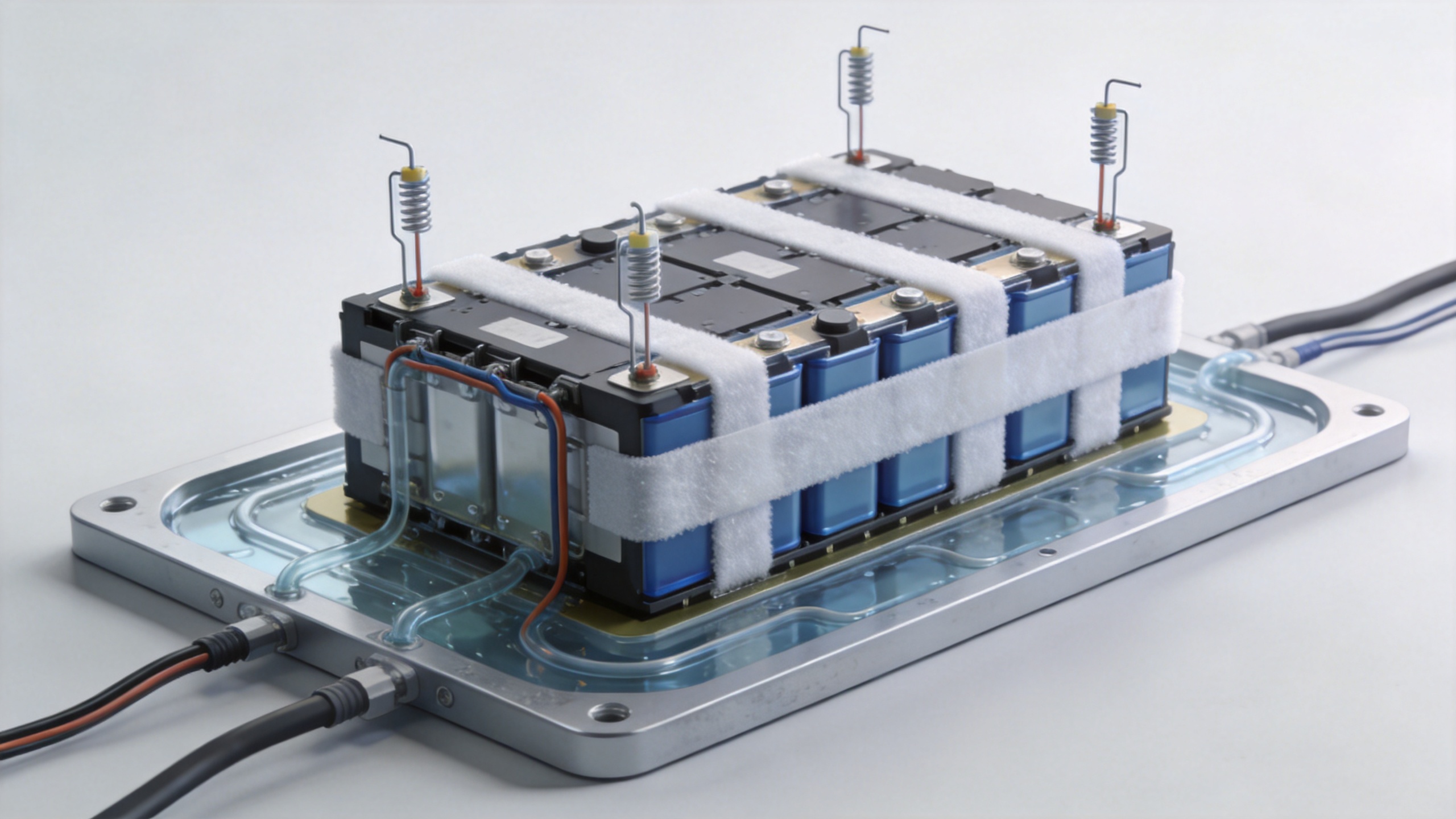
A practical answer to how to control battery test temperature uses two measurement roles. The control sensor drives the chamber or fluid loop. Independent verification sensors show what the battery experiences. For a small resting cell, air temperature may eventually track the cell. Under load, or in a large module, surface temperatures can diverge because of internal heat, insulation, busbars, and unequal contact with the fixture.
Install verification sensors at representative locations selected from the battery design and thermal review. Use the same attachment method, lead routing, and position notation each time. When deciding how to control battery test temperature, look for the slowest-responding area and likely hot spots rather than using only the most convenient location.
The chamber or coolant reading is an input to the test. The measured battery readings are the evidence. If they do not agree, do not assume the battery is ready simply because the controller reached its setpoint.
Select an appropriate thermal boundary
How to control battery test temperature also depends on how heat enters and leaves the test article. An environmental chamber can suit air-temperature exposure, cycling, and multiple samples. Its performance depends on airflow, chamber loading, sample spacing, cable heat paths, and the time needed for the battery to respond.
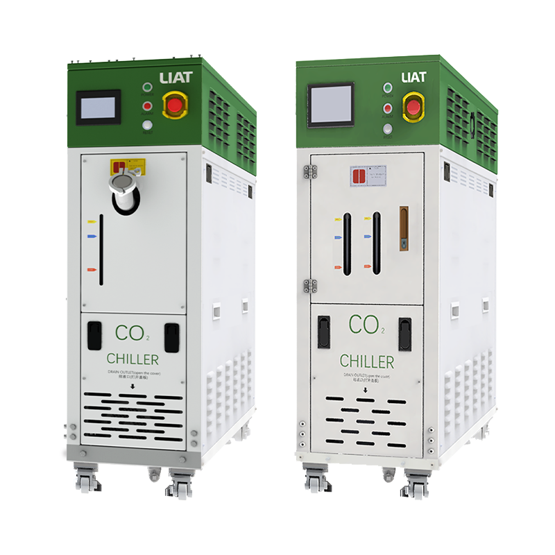
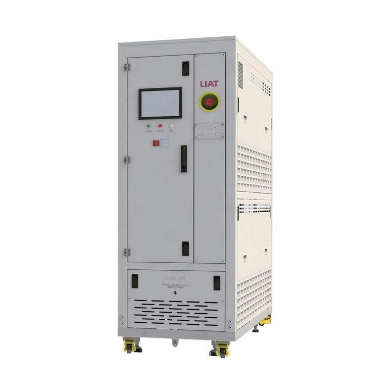
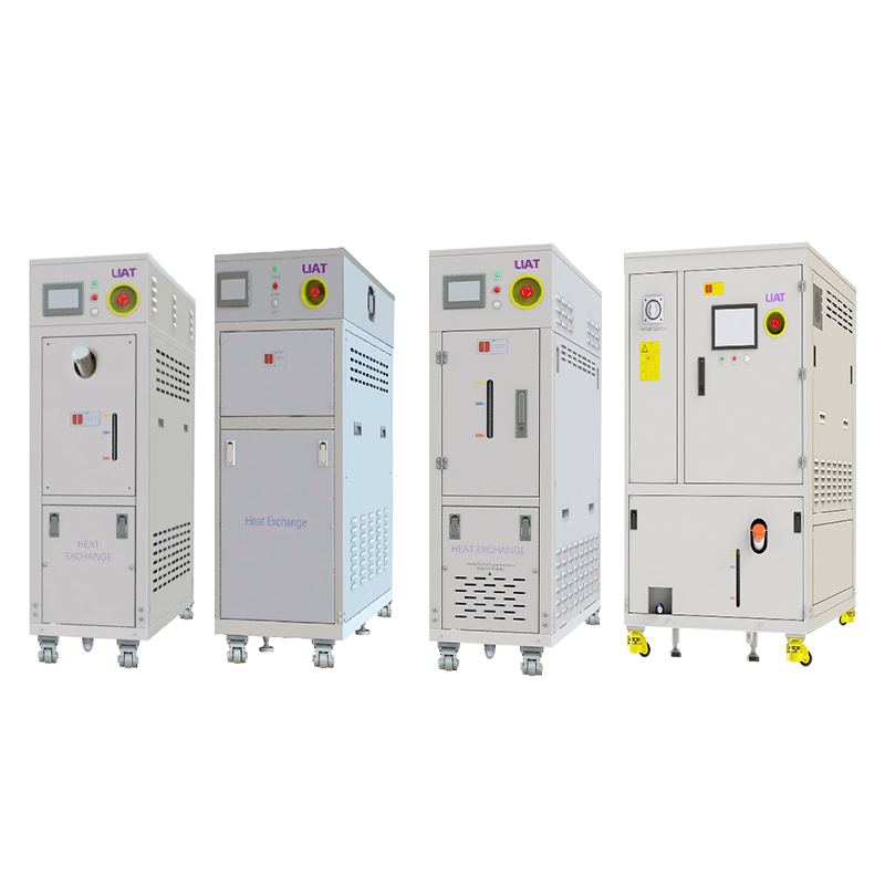
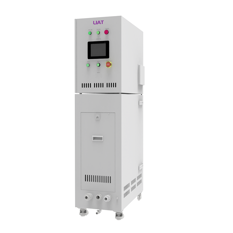
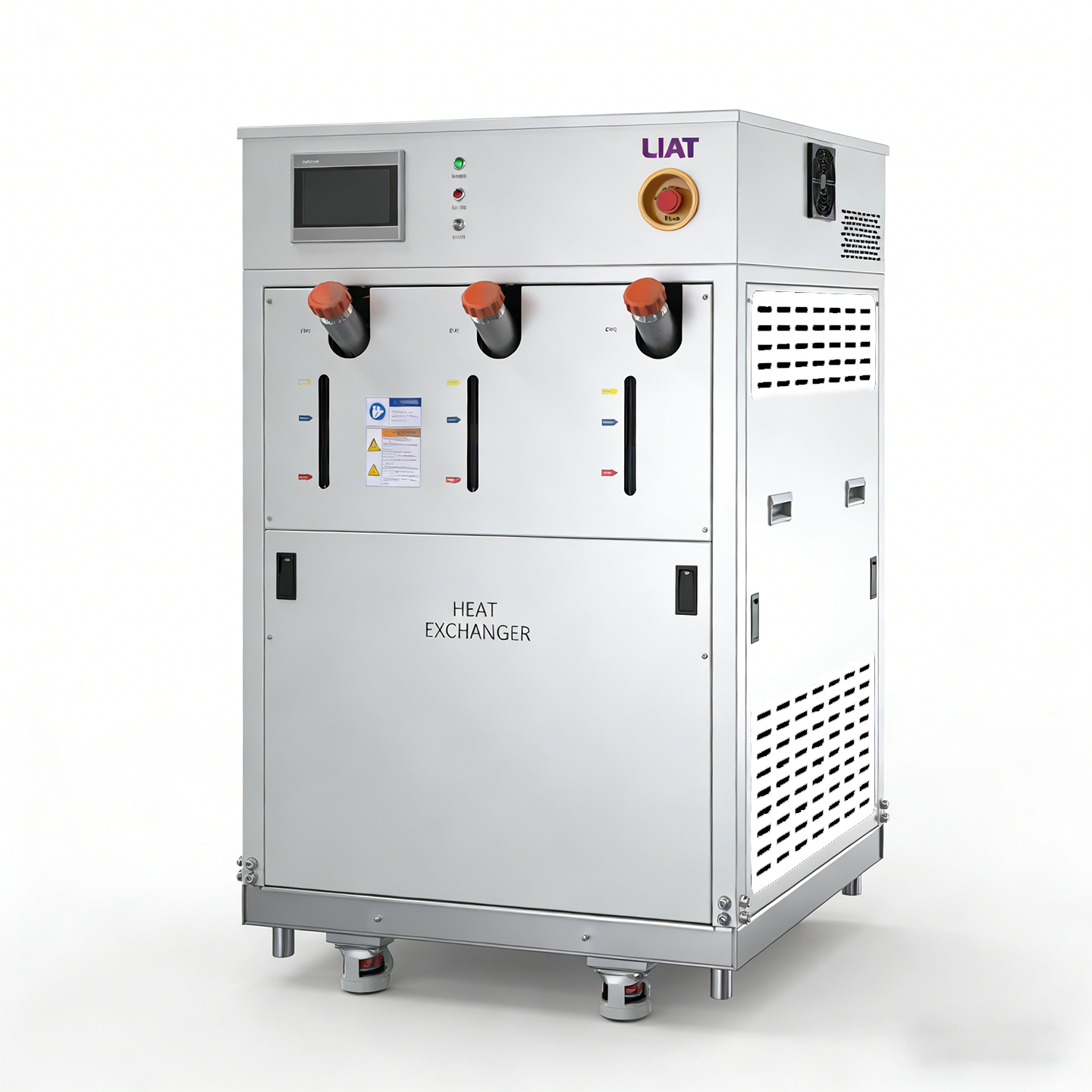
A liquid-cooled plate or jacket can offer a more direct thermal path when the fixture needs controlled fluid circulation. In this case, an industrial chiller provides a stable supply condition for the fixture. When using an industrial chiller, specify fluid type, supply temperature, flow, return temperature, hose insulation, pressure drop, and contact quality. An industrial chiller setpoint remains a boundary condition; it is not a substitute for battery-sensor verification.
Before committing to a method, estimate steady and transient heat load. A high-current pulse may create heat faster than an air system or fluid loop can remove it. Conversely, a large fixture can continue cooling or heating after a setpoint change. This thermal lag is central to how to control battery test temperature under real duty cycles.
Establish temperature stability before the electrical profile
Another essential part of how to control battery test temperature is a measured dwell rule. Do not use a fixed waiting time merely because it worked on a different cell or fixture. Review the recorded sensor trends and begin the next segment only when the required battery readings remain inside the allowed band for the specified duration.
For a temperature transition, use an orderly sequence: change the chamber or coolant target, wait for battery measurements to stabilize, confirm the sensor spread, then start the electrical profile. This approach to how to control battery test temperature distinguishes thermal equilibration from controller arrival.
Tune for stable response rather than display perfection
When refining how to control battery test temperature, avoid chasing every sensor fluctuation with aggressive controller settings. Excessive gain can cause oscillation, while too little response can leave the battery outside tolerance after a load change. Use representative no-load and loaded trials to review ramp response, overshoot, and recovery.
For liquid systems, record supply and return temperatures with flow. A growing difference can reveal changing heat transfer demand. For chambers, compare air and battery-surface traces across locations. These trends provide a more useful basis for how to control battery test temperature than a single controller number.
Use this commissioning checklist
- Translate the applicable procedure into target, tolerance, dwell, and alarm rules.
- Select the chamber, plate, or industrial chiller loop based on the required thermal boundary and expected heat load.
- Identify one control sensor and independent battery verification sensors.
- Check fixture contact, insulation, airflow or fluid routing, and cable heat paths.
- Run a representative characterization and record lag, gradients, and recovery.
- Verify the measured dwell criterion before each critical electrical segment.
- Log setpoint, control value, battery temperatures, current, voltage, flow where applicable, and alarms on one time base.
- Repeat characterization after a change to hardware, fixture contact, sensor placement, or duty cycle.
Common troubleshooting questions
Why is the battery warmer than the chamber?
In how to control battery test temperature, this usually indicates internal heat generation, thermal resistance to the environment, or insufficient dwell. Inspect current profile, contact pressure, airflow, and sensor placement before comparing electrical results.
Why do repeat runs disagree after a fixture change?
Fixture contact, fluid routing, cable routing, or sensor attachment may have changed the thermal path. Re-run the characterization; this is a normal part of how to control battery test temperature.
When is a liquid loop useful?
A liquid loop with an industrial chiller can be useful where direct heat transfer through a plate or jacket is needed. Its suitability depends on the procedure, fixture, fluid circuit, and measured battery response.
Document the thermal evidence
The dependable way to control battery test temperature is to treat temperature as a verified test condition, not a background setting. Define the requirement, select a meaningful control boundary, measure representative battery locations, account for heat load, confirm stabilization, and retain the time-aligned data. This disciplined workflow supports clear interpretation whether the setup uses chamber air, a thermal plate, or an industrial chiller.
Before a formal run, review the target window, sensor plan, thermal boundary, duty cycle, and safety logic together. That review helps the team decide whether a result reflects battery behavior or a change in the test thermal path.
 Hot News