
Why Semiconductor Chiller Contamination Control Protects Yield
In semiconductor equipment, a temperature loop is not merely a utility. It is part of the process environment. A semiconductor chiller does not necessarily contact a wafer directly, yet contamination in its fluid circuit can still disturb temperature control, flow stability, maintenance intervals, and the predictability of the tool it supports. From an equipment-integration perspective, that is why contamination control belongs in the same conversation as setpoint stability and heat load.
The important distinction is that “clean” is not a universal setting. The acceptable fluid condition depends on the process, the fluid chemistry, wetted materials, heat-exchanger design, and the separation between the thermal loop and the process. A well-designed contamination plan defines those boundaries first, then verifies them with trends rather than relying on a single startup measurement.
How a semiconductor chiller can turn contamination into yield risk
A semiconductor chiller removes or adds heat through a circulating medium. When that medium carries particles, corrosion products, dissolved contaminants, microbial growth, or incompatible additives, the immediate symptom may be subtle: rising pressure drop, unstable flow, slower response, fouling at a heat-transfer surface, or a filter that loads sooner than expected. The downstream consequence can be less stable process conditions.
That does not mean every cooling-loop excursion creates a wafer defect. The causal chain must be demonstrated for the specific tool and process. Still, semiconductor manufacturing is sensitive to repeatability. If a thermal loop gradually loses heat-transfer efficiency or produces intermittent flow restrictions, a tool may spend more time recovering from disturbances. That can make process windows harder to hold and makes root-cause work more difficult when yield drifts.
Particles matter because they can accumulate at small passages, valve seats, pumps, and heat-exchanger surfaces. Corrosion products can create a similar burden while also signaling a material or chemistry mismatch. Microbial growth is more often associated with less tightly controlled water systems, but the broader lesson applies to any wetted circuit: deposits can retain debris and reduce heat transfer. A recirculating chiller should therefore be evaluated as a managed fluid system, not just as a refrigeration package.
Contamination control begins with loop boundaries
For a semiconductor chiller, the loop boundary also determines which monitoring signals have meaning. A facility-side industrial chiller loop may be judged by broad utility-water control, while a process chiller circuit can require a more restrictive, tool-specific approach. A recirculating chiller should be commissioned against its own fluid specification and operating baseline.
The first engineering question is simple: what fluid is circulating, and where can it go? A process-facing high-purity circuit has a different risk profile from a facility-adjacent loop that transfers heat through a secondary exchanger. Mixing those requirements produces either unnecessary complexity or insufficient control.
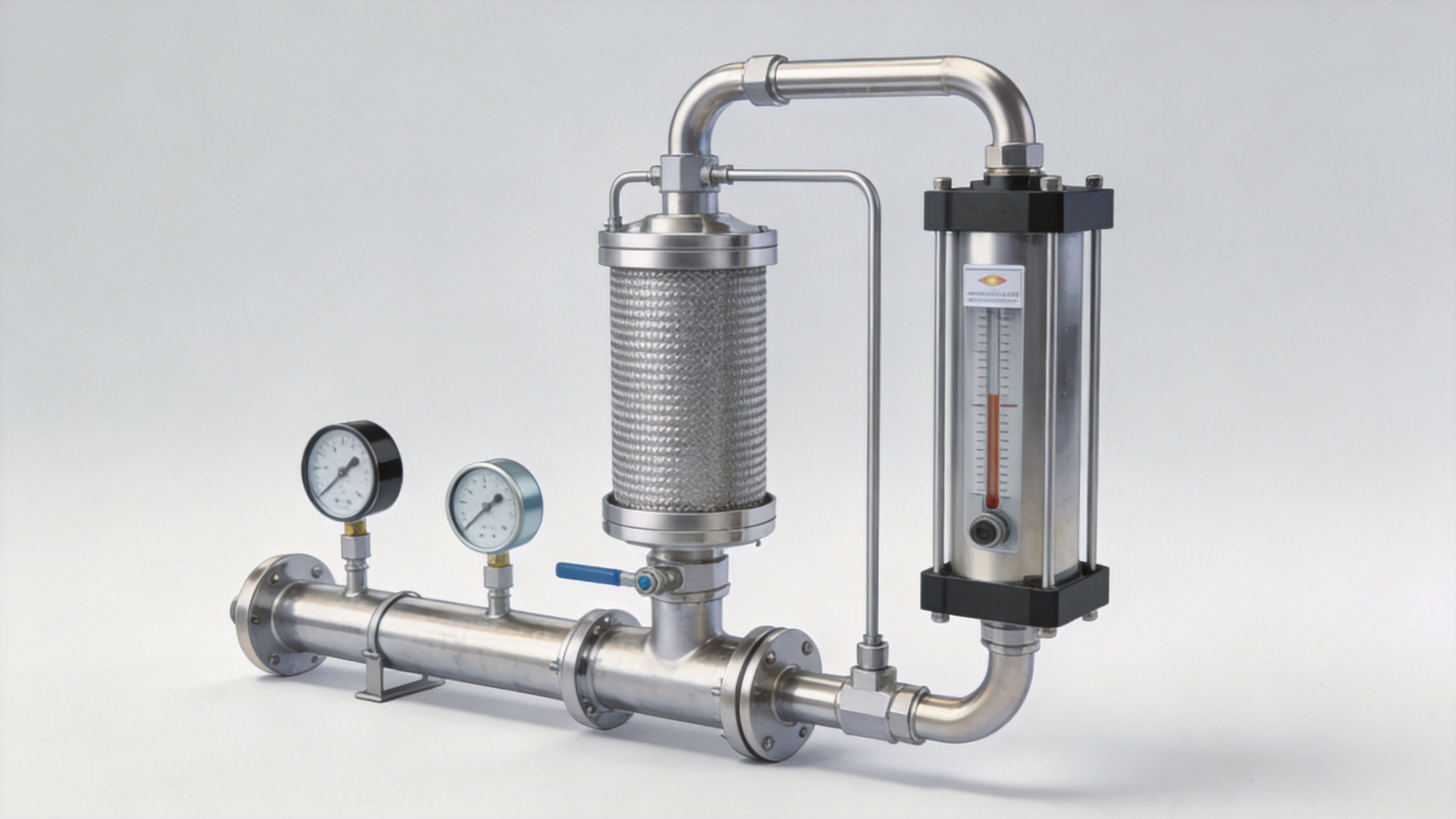
- Map the wetted path. Identify reservoirs, pumps, filters, hoses, valves, heat exchangers, sensors, and tool interfaces. Each material and connection is a possible source of particles, extractables, corrosion, or air ingress.
- Define the fluid specification. Establish applicable limits and test methods for the actual process, rather than borrowing values from another fab area or another industrial chiller installation.
- Separate incompatible loops. Where the process requires it, use appropriate isolation and secondary-loop architecture so facility-water variability is not carried into the process-facing circuit.
- Protect service actions. Fluid top-offs, hose replacement, filter changes, and maintenance flushing are contamination events to plan, document, and verify.
High electrical resistivity, for example, is useful information for certain fluids but is not a complete cleanliness verdict. It does not independently describe particle burden, nonionic organic contamination, dissolved gases, or microbial activity. The monitoring plan needs to match the failure mechanisms that matter at that point in the system.
Why heat-transfer surfaces deserve special attention
A semiconductor chiller loses useful control margin when contaminants settle where the thermal circuit expects open flow and clean heat transfer. In a recirculating chiller, the first visible evidence may be pressure drop or recovery time rather than a dramatic temperature excursion. That is why a process chiller maintenance record should connect filter condition, service work, and thermal behavior.
A clean heat exchanger transfers heat more predictably than one carrying deposits. Even a thin fouling layer adds thermal resistance; if it grows unevenly, the effect can be dynamic rather than obvious. The control system may compensate for a while, but compensation does not remove the underlying loss of margin.
For a semiconductor chiller, this is especially relevant when the tool has changing thermal loads or tight temperature-recovery expectations. A restrictive filter, a partially fouled exchanger, or gas entrainment can alter flow and response characteristics. Instead of treating a temperature alarm as an isolated refrigeration issue, maintenance teams should ask whether the fluid condition, material compatibility, or recent service history changed the thermal circuit.
Corrosion deserves the same systems view. It can introduce solids, weaken components, and create localized roughness that promotes further deposition. The remedy is not automatically a chemical addition. First confirm the fluid, material mix, oxygen exposure, temperature range, and treatment compatibility. In a process chiller application, a treatment decision that is acceptable for a general utility loop may be inappropriate for a high-purity or process-adjacent loop.
A practical contamination-control sequence
- Set a risk-based baseline. At commissioning or after a major intervention, record relevant fluid, pressure-drop, flow, temperature-response, and filter-condition observations. The baseline should be tied to the actual tool condition.
- Use staged barriers. Appropriate filtration, loop isolation, controlled fill procedures, compatible materials, and clean service practices work together. No single filter rating replaces this combination.
- Trend, do not only test. A one-time acceptable sample can miss a developing problem. Watch changes in differential pressure, flow behavior, temperature approach, particle results where applicable, and repeat maintenance findings.
- Investigate deviations at the source. If contamination rises, trace the likely ingress route: makeup fluid, a maintenance connection, degrading hardware, a treatment incompatibility, or a stagnant section of the circuit.
- Verify recovery before returning to critical use. Flushing or component replacement should be followed by checks that match the identified risk, not simply by resetting an alarm.
The sequence is useful because it connects fluid cleanliness to thermal performance. It also avoids a common error: treating a process chiller as maintenance-free until cooling capacity visibly falls. By that point, the system may already have lost operating margin.
What to specify when evaluating an industrial chiller for semiconductor work
When an industrial chiller is proposed for semiconductor support, the question is not whether it is generally capable of cooling. The question is whether the semiconductor chiller fluid path and service controls preserve the required process boundary. This comparison prevents a general industrial chiller from being assumed equivalent to a process chiller without evidence.
An industrial chiller may be suitable for supporting equipment only when its fluid path, materials, controls, and service model fit the required cleanliness level. Procurement and integration teams should request a clear description of wetted materials, reservoir configuration, filtration approach, drain and fill procedures, sensor locations, allowable fluids, and the method for isolating the tool from upstream variability.
Ask for conditions rather than promises. For example: What fluid assumptions apply to the stated performance? Which components are in contact with the circulating medium? How are filter-change intervals determined? What measurements can reveal declining flow or rising restriction? How is air removed after maintenance? These questions make the contamination-control plan testable.
Contamination control is a yield-protection discipline
A semiconductor chiller control plan is more effective when it is reviewed with the tool owner, facilities team, and maintenance team together. The recirculating chiller data should show whether the process chiller is behaving consistently, while any industrial chiller interface is checked for upstream change. These are verification practices, not a guarantee that thermal control alone determines yield.
Yield protection is rarely the result of one component alone. It comes from preserving stable, repeatable conditions across the tool, interfaces, utilities, and maintenance practices. A semiconductor chiller supports that objective when its loop remains compatible with the process, its contamination risks are understood, and its condition is trended before a small restriction becomes a larger process disturbance.
For that reason, the next step is not to select a generic cleanliness target. It is to build a loop-specific control plan around the process, fluid, materials, interfaces, and verification points. That plan gives engineering and operations teams a shared way to protect thermal consistency—and, in turn, protect the yield-sensitive work the tool performs.
 Hot News