How a Semiconductor Heat Exchanger System Handles Process Fluids
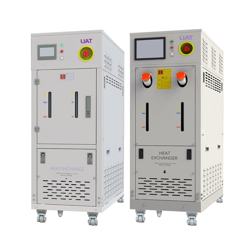
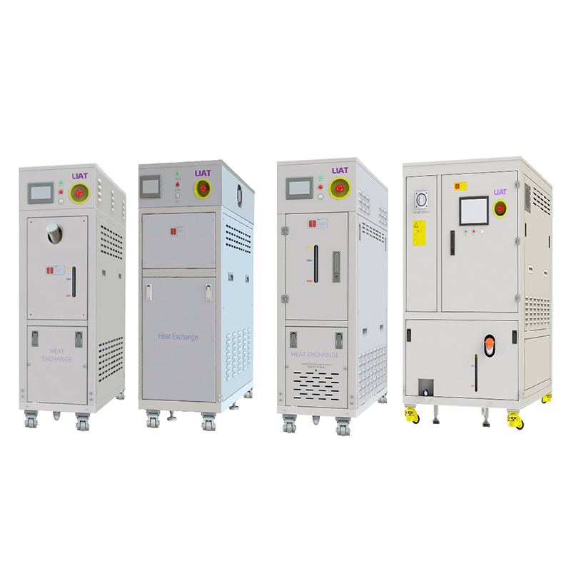
A semiconductor heat exchanger system moves heat between controlled fluid loops while keeping the process side isolated from the utility side. In a wafer-fab setting, that job is more demanding than ordinary comfort cooling: the fluid may need tight temperature stability, low contamination risk, compatible wetted materials, and predictable pressure loss. From a semiconductor equipment-integration perspective, the useful question is not simply whether a heat exchanger can transfer heat. It is whether the semiconductor heat exchanger system fits the actual fluid, load, connections, and control sequence.
A conventional heat exchanger transfers thermal energy across a solid wall. In semiconductor equipment, that wall can separate a tool loop from a facility-water, chilled-water, or secondary-loop circuit. The separation lets engineers manage temperature without mixing fluids, but it also makes flow arrangement, cleanliness, and instrumentation part of the performance discussion.
Start with the process fluid, not the exchanger style
The first task in specifying a semiconductor heat exchanger system is to describe the fluid on each side of the thermal boundary. Water-based cooling media, treated water, glycol mixtures, dielectric fluids, and chemical-service streams each create different questions. Fluid chemistry, temperature range, allowable particles, conductivity requirements, and compatibility with seals and wetted metals should be confirmed before a size or construction is selected.
This matters because a semiconductor heat exchanger system can appear thermally adequate on a data sheet yet be a poor fit for the loop. A fluid with changing concentration may alter viscosity and pressure drop. A stream with demanding purity requirements may call for a different approach to material selection, cleaning, and commissioning. Where corrosive process chemistry is involved, compatibility needs review against the actual concentration, temperature, and exposure time rather than a generic material label.
How the thermal path works
In a typical semiconductor heat exchanger system, warmer process fluid enters one flow path while a cooler utility or secondary fluid enters another. Heat passes through the separating wall, and the two fluids leave at new temperatures. The system does not create cooling by itself; it transfers a thermal load to the loop that can absorb and reject it.
The thermal result depends on more than inlet temperatures. Engineers normally map the required heat duty, both flow rates, permitted approach temperature, fluid properties, fouling allowance, and acceptable pressure drop. A thermal transfer assembly that has excess thermal area may still cause an operational problem if its pressure loss drives a pump outside its workable range. Conversely, a compact unit with a low initial pressure drop needs enough margin for real operating conditions and maintenance intervals.
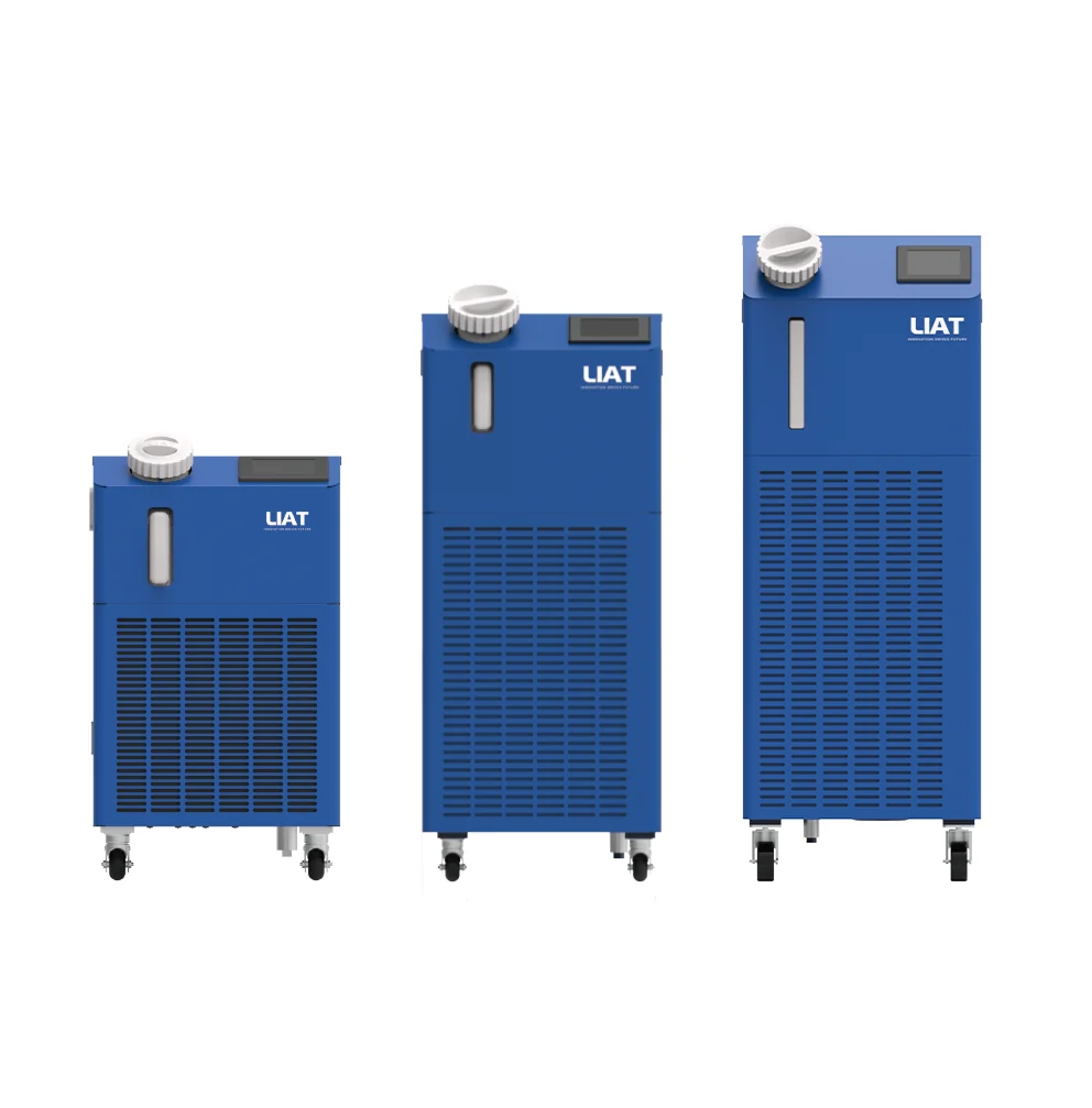 Process-fluid and utility loops exchange heat across an isolated thermal boundary.
Keep the tool loop and facility loop distinguishable
Many process issues become easier to diagnose when the thermal transfer assembly is treated as the boundary between two responsibilities. The tool-side loop must meet the process equipment’s fluid and temperature needs. The facility-side loop must supply stable capacity at the agreed inlet conditions. If either side changes, the temperature leaving the exchanger can drift even when the exchanger itself is mechanically sound.
That distinction guides instrumentation. Temperature sensors at both inlets and outlets reveal whether the duty is moving as expected. Differential-pressure measurements across the unit help identify rising resistance from fouling, a valve-position issue, or a changing flow condition. Flow confirmation matters because temperature alone can mask a reduction in circulation. Trend these readings together; a single high temperature rarely explains the full thermal path.
Why cleanliness and material compatibility affect thermal stability
Cleanliness is not merely a maintenance preference. Deposits, corrosion products, and particles can increase resistance to heat flow and narrow passages over time. For a semiconductor heat exchanger system, the commissioning plan should define flushing, filtration, sampling, and acceptance checks appropriate to the fluid loop. The exact procedure belongs to the project’s contamination-control requirements, not to a generic maintenance schedule.
Material decisions follow the same logic. Search results and industry application information commonly associate ultrapure-water cooling with semiconductor and electronics duties, while chemically demanding services may require corrosion-aware construction. Those observations are useful starting points, not a substitute for a compatibility review. The selected exchanger assembly should be reviewed with the supplier and process owner using confirmed fluid data and the site’s purity limits.
Control integration determines how the system responds
This equipment is often part of a larger temperature-control chain that includes pumps, valves, a chiller or facility utility, sensors, and equipment controls. The exchanger changes temperatures through heat transfer; the control architecture decides how quickly and consistently the loop responds to load changes.
Before startup, agree on sensor locations, control targets, alarm limits, flow interlocks, and the intended response to utility variation. It is also worth clarifying which controller owns each valve or pump command. Without that boundary, two control loops can react to the same deviation in ways that increase rather than settle temperature variation. A commissioning sequence should test stable load, stepped load, reduced flow, and utility-temperature changes within approved operating limits.
A practical evaluation checklist
Use the following questions to evaluate the proposed thermal transfer assembly before final configuration:
- What are the confirmed process-fluid composition, cleanliness limits, temperature range, and flow range?
- What heat duty is expected at normal, minimum, and peak operating conditions?
- What inlet conditions can the facility or secondary loop reliably provide?
- What pressure drop is acceptable on each side of the unit?
- Which materials, seals, cleaning methods, and filters are compatible with the process fluid?
- Which temperatures, flows, and differential pressures will be trended after commissioning?
- How will the equipment respond if flow falls or the utility inlet temperature moves outside its agreed range?
Make operating evidence part of the decision
The most dependable way to assess a semiconductor heat exchanger system is to connect its thermal design to operating evidence. Compare measured inlet and outlet temperatures, confirmed flow, differential pressure, and the tool’s load condition. Then review deviations in context: a warmer outlet might reflect higher heat duty, reduced utility capacity, lower flow, or a developing resistance issue.
That evidence-based approach keeps the semiconductor heat exchanger system discussion focused on the process fluid and the full loop rather than on a single headline specification. When fluid properties, thermal duty, pressure limits, cleanliness needs, and controls are defined together, engineering teams can make a clearer configuration decision and establish a more useful baseline for future troubleshooting.
 Hot News