
What a Battery Test Cooling Unit Controls During Cycling
During charge and discharge cycling, a battery test cooling unit does more than make a test bench colder. In a liquid-cooled setup, it establishes the thermal boundary condition at the battery cooling circuit: the temperature of the supplied heat-transfer fluid, its circulation rate, and, where the rig supports it, its pressure. Those controlled conditions help engineers separate the battery’s behavior from uncontrolled changes in its test environment.
That distinction matters. A battery can heat itself as current, state of charge, resistance, and ambient conditions change. If the thermal boundary shifts at the same time, it becomes harder to decide whether a change in voltage, power, or temperature came from the unit under test or from the test setup. As a thermal-management engineer would frame it, first confirm the operating condition; only then interpret the result.
Start by separating coolant-loop control from chamber control
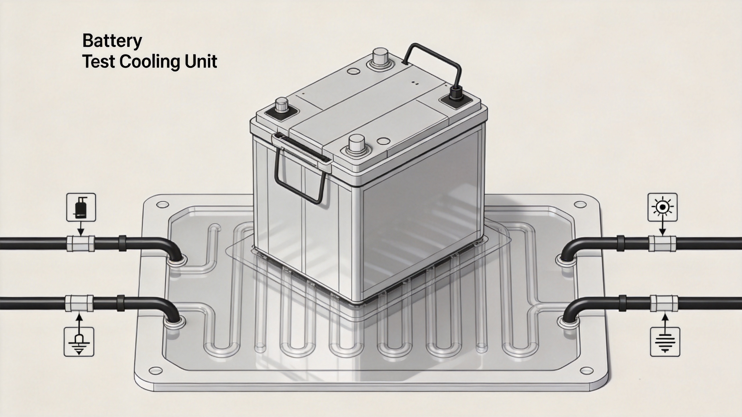
A battery test cooling unit is commonly used when a cell, module, or pack has a liquid cooling plate or another external thermal circuit. It circulates conditioned fluid through that circuit. A temperature chamber performs a different job: it controls the air surrounding the test article. Some programs use one approach, some use both, and some need neither. The test method and the battery hardware decide which boundary condition is relevant.
An industrial chiller may supply cooling for a loop, but the label alone does not describe the complete test function. A cycling application may need heating as well as cooling, programmable transitions, stable flow, pressure management, instrumentation interfaces, and alarms. The practical question is not “Is there a chiller?” It is “Which variables must the rig hold or record while the battery cycles?”
The primary variable: coolant supply temperature
The first control target of a battery test cooling unit is usually the coolant temperature delivered to the battery inlet. The test program can hold that inlet condition at one target or move it through scheduled setpoints. This makes the coolant loop a repeatable boundary condition for evaluating a battery thermal-management path.
Supply temperature is not automatically the same as cell temperature, module temperature, or the temperature reported by the battery management system. Heat must travel through coolant, plates, interfaces, housings, and cells. Sensor location, flow distribution, and time delay all affect the difference. For that reason, a report should state which temperature is controlled and where it is measured rather than treating a single setpoint as the condition of every component.
Flow rate: controlling heat transfer conditions
In a liquid circuit, the battery test cooling unit also needs an appropriate flow condition. Flow rate affects how quickly heat-transfer fluid transports heat from or toward the battery cooling plate. A low flow can increase the temperature rise between inlet and outlet; a high flow can change hydraulic losses, pump demand, and the distribution between parallel paths.
Flow is therefore more than a plumbing detail. When cycling current changes, the battery heat load can change with it. Keeping a defined flow rate makes inlet-to-outlet temperature difference and thermal response easier to compare across runs. If the system only monitors flow rather than actively regulating it, that limitation belongs in the test record.
Pressure and circuit integrity
Many battery cooling loops have pressure limits or a specified operating range. Depending on the rig, the battery test cooling unit may regulate pressure, monitor it, or simply provide a pump whose operating point is checked by the operator. Pressure data can reveal restrictions, leaks, trapped air, or a changing circuit condition, but it should not be interpreted alone.
Before a cycling sequence begins, confirm the required pressure range, compatible fluid, hose routing, fittings, and bleed procedure for the battery fixture. These items are often overlooked when teams focus only on the temperature setpoint. Yet a stable temperature target has limited value if the loop contains air pockets or if the flow is not reaching the intended cooling channels.
Heating and cooling capacity during charge and discharge
A battery test cooling unit must handle the direction and size of the heat load expected during the program. During a high-current discharge or charge segment, the unit may need to reject heat while keeping the coolant near its scheduled condition. During cold-condition work or a transition to a warmer setpoint, it may need heating capacity instead. The duty is dynamic, not a single nameplate number.
Capacity selection starts with the expected electrical cycling profile, estimated heat generation, target temperature range, fluid properties, and the thermal mass of the battery and fixture. Include heat picked up from hoses, manifolds, and the surrounding room where it is relevant. A compact industrial chiller can be suitable for some loops, but a thermal-control system should be assessed against the actual transient load and required temperature stability, not just nominal cooling capacity.
What the unit measures versus what it controls
A useful test plan separates closed-loop controls from recorded channels:
- Usually controlled: coolant supply temperature; sometimes flow rate and loop pressure.
- Usually measured: coolant return temperature, battery surface temperatures, cell or module temperatures, ambient temperature, electrical current, voltage, and state-of-charge signals.
- Program-dependent: ramp rate, dwell time, heating enablement, pump speed, and alarm limits.
This distinction avoids a common reporting error: claiming that the battery test cooling unit “controls battery temperature” when it actually controls a coolant condition and observes how the battery responds. Direct battery-temperature control is possible only when the complete hardware, sensor placement, and control strategy support it.
How cycling programs use those controls
A cycling program typically coordinates an electrical cycler with the thermal system. Before each segment, the test bench establishes the requested coolant condition. During the segment, the battery test cooling unit maintains its controlled variables within the agreed tolerance while the data system records the response. At the end of the segment, engineers compare inlet and outlet coolant data with battery temperatures and electrical data to understand the thermal behavior.
For example, a program may hold a coolant inlet temperature while increasing discharge current. If battery temperatures rise, the first check is not automatically the cooling unit. Review the actual inlet temperature, return temperature, flow, pressure, current profile, sensor positions, and timing. Temperature variation often begins with conditions, not one isolated component.
A pre-test checklist for the cooling loop
- Define whether the test needs ambient-air control, direct coolant-loop control, or both.
- Record the coolant type, inlet temperature target, allowable tolerance, and test-program ramps.
- Set or verify the required flow rate and pressure range for the fixture.
- Confirm that supply and return sensors are identified and time-synchronized with cycling data.
- Estimate the expected thermal load for each charge and discharge segment.
- Check alarms, interlocks, leak detection, and the response to loss of flow or temperature deviation.
- Document what is controlled, what is only monitored, and where every measurement is taken.
The practical takeaway
A battery test cooling unit controls the coolant-side conditions that make battery cycling tests comparable: primarily supply temperature, and often flow and pressure as the rig requires. It does not automatically make every part of the battery the same temperature. Its value is in creating a defined, traceable thermal boundary while the battery produces or absorbs heat during cycling.
For equipment selection, begin with the battery’s cooling architecture and the test protocol. Then map heat load, temperature range, flow, pressure, ramp behavior, sensing, and safety interlocks to the required thermal-control system. That condition-first approach produces more useful test data than choosing an industrial chiller solely by a catalog cooling number.
 Hot News