
How Motor Durability Testing Cooling Extends Test Validity
Motor durability work is intended to show how a machine behaves through repeated load, speed, torque, and environmental cycles. That goal is harder to reach when the thermal boundary drifts from one test segment to the next. Motor durability testing cooling is therefore more than a way to remove heat from a rig. It is part of the measurement condition that makes a long test interpretable.
From a thermal-management application engineer’s perspective, the first question is not simply whether the motor is cool enough. It is whether coolant temperature, flow, and heat rejection stay sufficiently controlled for the planned duty cycle. If the heat load changes substantially, a target temperature alone usually does not describe the condition. A sound motor durability testing cooling plan records the cooling condition alongside electrical, mechanical, and thermal measurements.
Why cooling conditions affect durability-test validity
A durability result is useful when another engineer can understand what the motor experienced. Winding temperature, housing temperature, bearing region temperature, inlet coolant temperature, and ambient conditions may all move during a run. If cooling capacity or control response changes without being observed, a change in temperature may be misread as a motor issue when it actually follows the test cell’s thermal behavior.
That distinction matters during long cycles. A motor can see a similar torque command in two test windows while entering each window at a different thermal starting point. The resulting temperature trace, resistance trend, or protection event may not be directly comparable. Stable motor durability testing cooling helps teams separate a component response from a facility-side disturbance.
Common rotating-machine temperature-rise contexts use the temperature of the cooling medium in the interpretation of results. Many rating discussions also use a 40°C reference ambient assumption. In a durability laboratory, however, that reference should not replace the actual condition log. The useful question is: what was the air or liquid temperature at the motor boundary during this particular segment?
What controlled cooling contributes to a repeatable test
A controlled loop gives the test team a known thermal starting point and a clearer response after each load transition. It does not make every test result identical; motor design, instrumentation position, flow path, and duty cycle still matter. It does make the operating context easier to compare across samples, revisions, and repeat runs.
- Defined inlet condition: Record the coolant or air condition at the point relevant to the motor or fixture, not only at the cooling unit.
- Visible load response: Trend inlet and outlet temperatures, flow where applicable, and controller output through torque and speed changes.
- Controlled recovery: Use a documented cool-down criterion between sequences instead of relying on elapsed time alone.
- Traceable exceptions: Mark alarms, controller saturation, flow interruptions, or changes to the test-cell configuration in the data record.
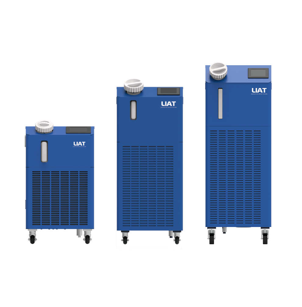
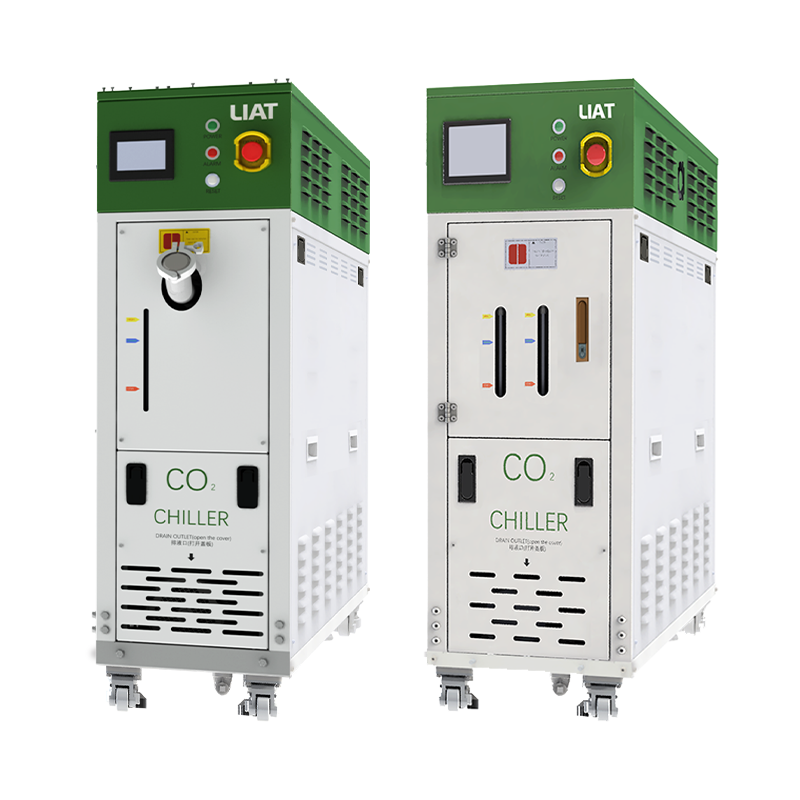
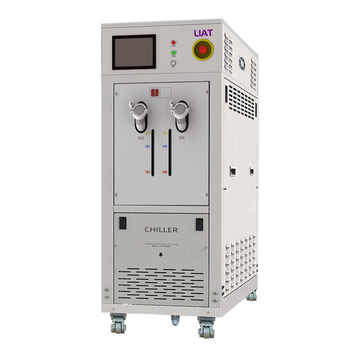
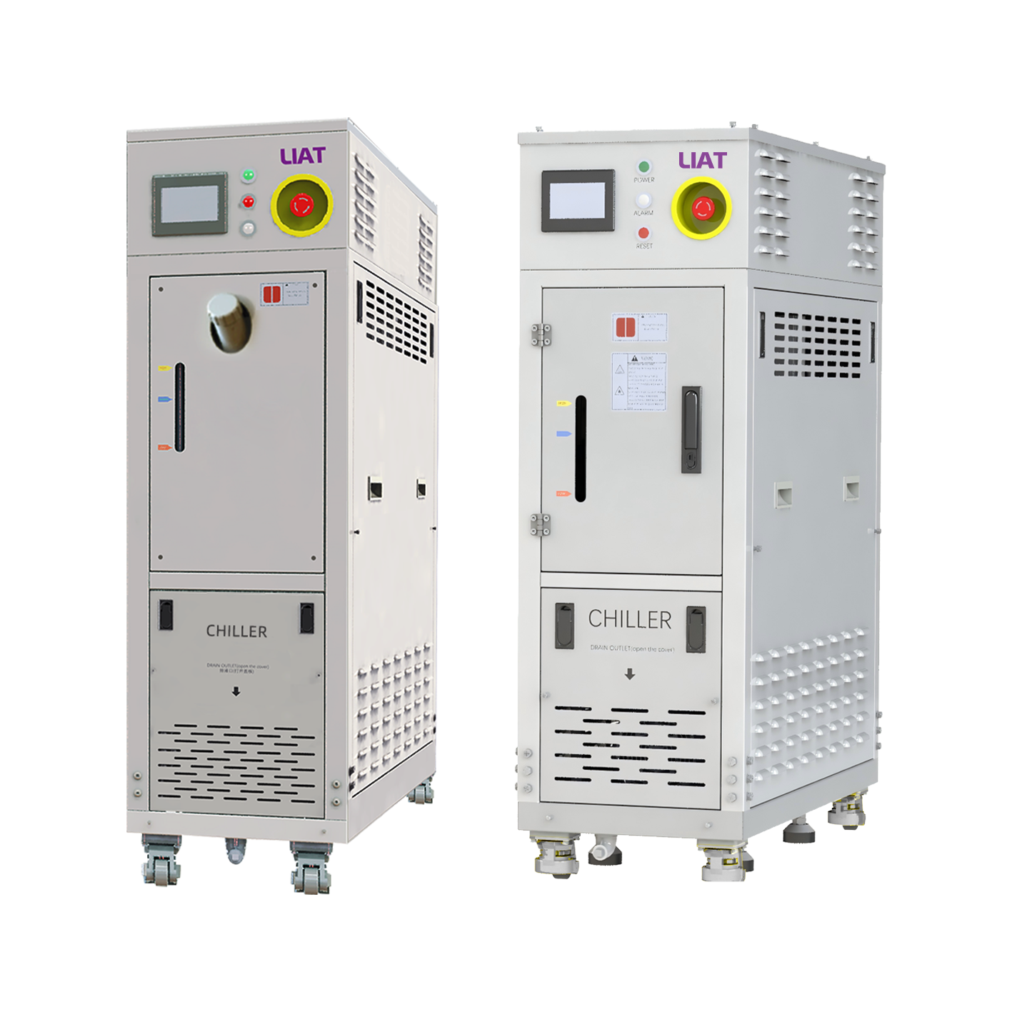
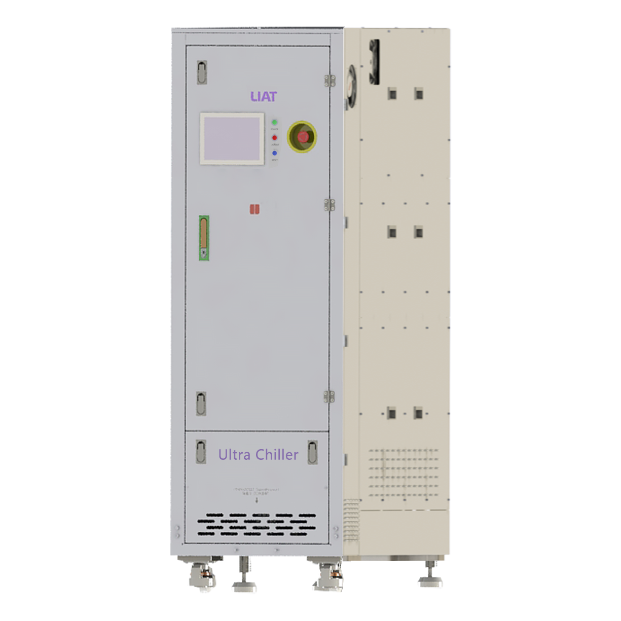
An industrial chiller may be part of that loop when a test bench needs recirculated liquid at a defined operating condition. Its suitability depends on the target temperature range, changing heat load, fluid compatibility, piping volume, pressure drop, control connection, and maintenance plan. Those inputs should be reviewed together rather than inferred from a single cooling-capacity figure.
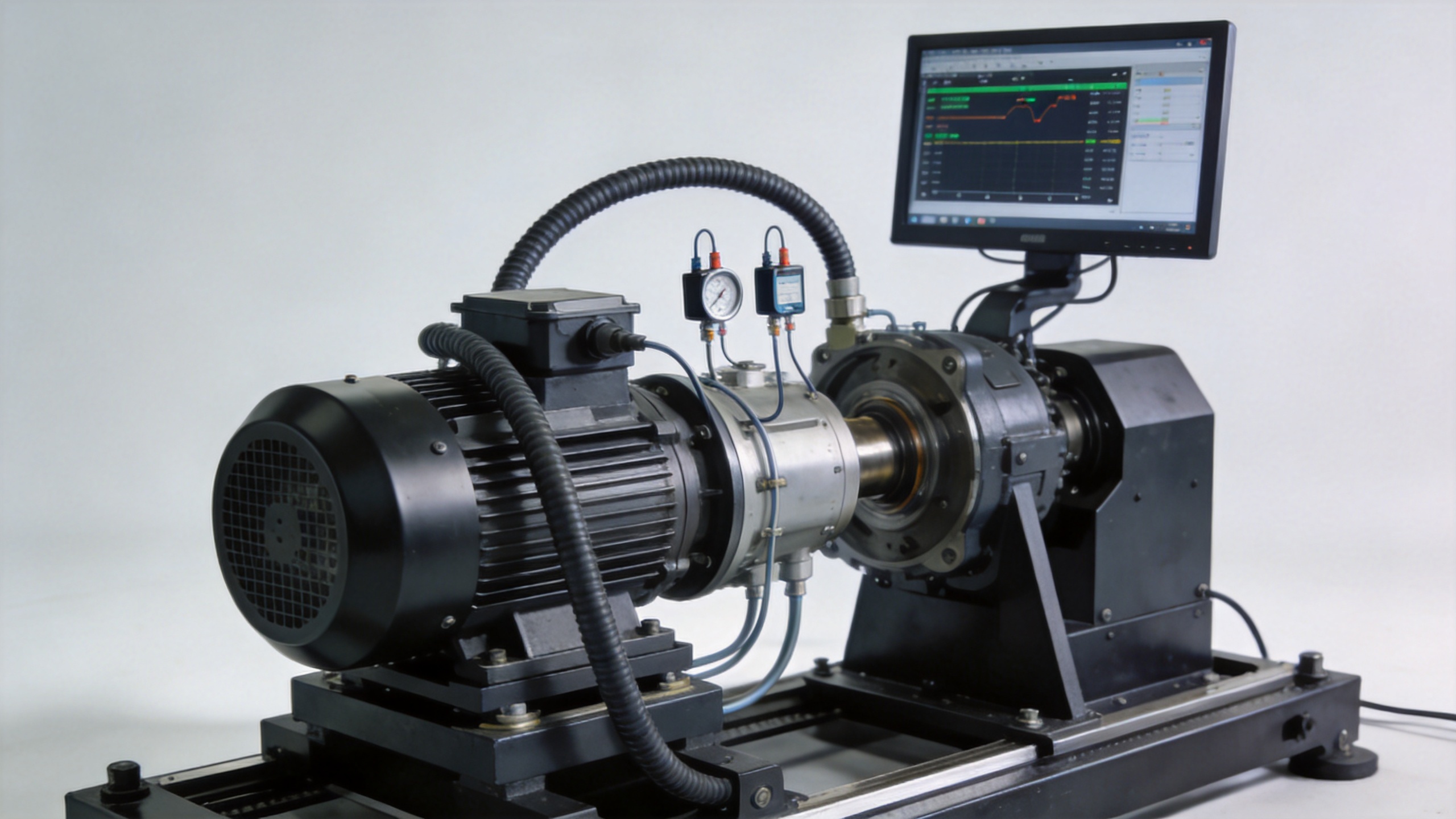
Build the cooling plan around the duty cycle
Good motor durability testing cooling begins with the test profile. Identify steady-state plateaus, rapid accelerations, regenerative events if present, soak periods, and expected heat-rejection peaks. Then decide which values must remain controlled and which values must merely be measured. This prevents a common problem: specifying a narrow coolant setpoint while overlooking a transient load that the loop cannot absorb at the required response time.
For an anonymous test-cell scenario, consider a motor that runs repeated high-load intervals followed by low-load stabilization. A cooling loop that appears stable during the low-load period may lag after each high-load interval. If the data system only stores periodic averages, that lag can disappear from the report even though the winding or case temperature experienced a meaningful excursion. Higher-resolution synchronized logging can reveal whether the excursion tracks motor input, coolant inlet temperature, flow, or controller response.
From common engineering communication practice, checking heat load first often reduces later rework. Estimate the expected rejection range, then compare it with the cooling loop’s usable range at the intended fluid, temperature, piping configuration, and ambient condition. Treat the result as a verification input, not as a universal conclusion.
Instrumentation turns cooling into evidence
The value of motor durability testing cooling rises when its measurements are aligned with the rest of the bench. Give each channel a clear location, unit, sampling rate, calibration status, and time basis. At minimum, many teams review inlet temperature, outlet temperature, flow or pressure indication where relevant, motor case temperature, electrical input, speed, torque, and test-state markers.
Sensor placement deserves attention. A sensor on a reservoir or distant manifold can be useful for system health but may not represent the medium arriving at the motor fixture. Likewise, a motor case sensor can support trend analysis but does not automatically stand in for winding temperature. Note these boundaries in the test plan so later reviewers do not draw stronger conclusions than the instrumentation supports.
When an industrial chiller is used, synchronize its alarms and control-state information with the bench historian if the connection permits it. A temperature excursion is easier to investigate when the record shows whether it coincided with a flow alarm, a setpoint change, a load step, or a period of controller limitation.
A practical validation checklist
- Define the target cooling-medium condition and the allowable control band for each test phase.
- Map the expected heat-load range, including transients and recovery periods.
- Confirm fluid, wetted materials, piping volume, connections, and pressure-drop limits.
- Place sensors near the relevant thermal boundary and synchronize all channels.
- Run a shakedown profile, then compare cooling response with the planned duty cycle.
- Document any deviation, configuration change, or interruption before comparing durability results.
Make conclusions fit the evidence
Cooling does not replace a complete motor durability method. It supports one part of it: a better-defined thermal environment. For that reason, the conclusion from motor durability testing cooling should state the observed conditions, the measurement limits, and the test segments covered. If the cooling medium, flow path, or heat load changed, segment the data rather than presenting the run as one uniform exposure.
For teams planning a new bench or revising an existing one, start by collecting five items: target temperature range, heat-load profile, cooling medium, connection requirements, and maintenance access. That information creates a clearer basis for discussing an industrial chiller or another thermal-control approach and for deciding what evidence the durability program needs next.
 Hot News