
How a Motor Testing Chiller Holds Stable Temperatures
When a motor test is meant to compare designs, validate a duty cycle, or document a thermal limit, temperature drift can cloud the result. A motor testing chiller helps create a controlled thermal boundary around the device under test, the fixture, or the coolant loop. The aim is not merely to reach a setpoint. It is to hold test conditions steady enough that engineers can distinguish motor behavior from changes in the surrounding thermal system.
As a practical rule, the chiller should be treated as part of the test method. Heat generated by windings, bearings, power electronics, and the dynamometer may change during a run. Ambient conditions and coolant flow can change too. A well-matched motor testing chiller gives the test team a repeatable way to manage those influences while recording what actually occurred.
Stable temperature means more than a stable display
A controller can show a constant number while the motor, coolant, fixture, and sensors are still moving toward thermal equilibrium. For meaningful results, define which temperature matters and where it is measured. Depending on the objective, that may be coolant supply, coolant return, winding temperature, housing temperature, inverter temperature, or a chamber reference point.
This distinction matters because every thermal path has delay and resistance. If the motor load steps upward, the coolant supply may respond quickly while the winding temperature continues to rise. Conversely, a sudden cooling response can overshoot at the fixture before the motor core sees the change. The useful question is therefore: does the motor testing chiller keep the specified control point within the test tolerance while the rest of the system settles in a predictable way?
How a motor testing chiller supports repeatable tests
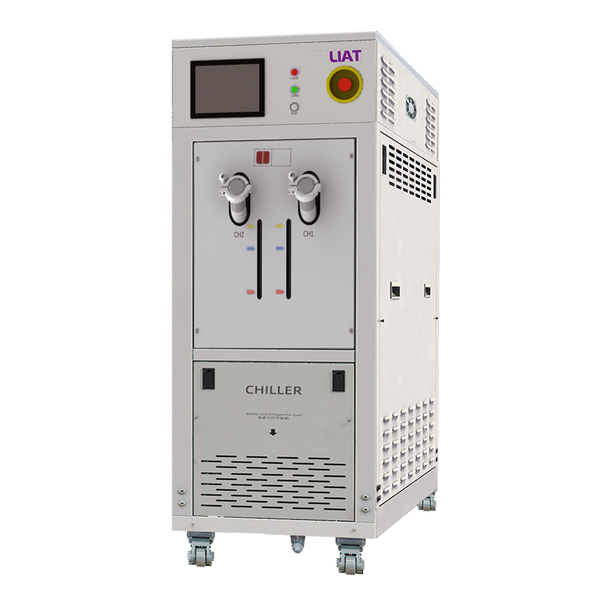
In a typical recirculating loop, the chiller removes heat from the test circuit and sends conditioned fluid back to the fixture. Its contribution to repeatability comes from four linked functions:
- Setpoint control: It maintains the chosen supply-temperature target during the stated test window.
- Heat-load response: It handles expected changes as speed, torque, voltage, or duty cycle changes.
- Flow continuity: It supports the required circulation conditions so the fixture transfers heat consistently.
- Data visibility: It provides operating values and alarms that can be reviewed alongside motor-test data.
An industrial chiller used for this purpose should be sized around the test profile rather than a single, assumed heat number. A steady endurance run, a rapid load sequence, and a start-stop cycle can place very different demands on the same thermal loop.
Start with the thermal test profile
Before selecting or configuring a motor testing chiller, map the test as a sequence instead of a single operating point. Ask what happens during warm-up, peak load, reduced load, dwell, and shutdown. The answers reveal whether the important issue is continuous capacity, transient response, cooling-and-heating coordination, or all three.
| Test input to confirm | Why it affects temperature stability |
|---|---|
| Target temperature range and tolerance | Defines the control objective and sensor accuracy needed for the method. |
| Heat-load range over time | Shows whether nominal capacity alone is sufficient for peaks and ramps. |
| Coolant type and required flow | Influences heat transfer, pump requirements, compatibility, and pressure drop. |
| Fixture and hose volume | Creates thermal lag that affects response and settling time. |
| Ambient conditions | Can add heat to exposed lines, fixtures, and the motor housing. |
| Data-acquisition timing | Ensures chiller data and motor data can be aligned during analysis. |
These inputs also keep comparisons honest. A motor that reaches a different final temperature may be responding to a different load, flow condition, or ambient environment rather than a design change alone. Published motor thermal-test work commonly records multiple temperatures, including winding, frame, and ambient readings, until steady-state conditions are reached. That practice illustrates why one chiller display should not be the only thermal record.
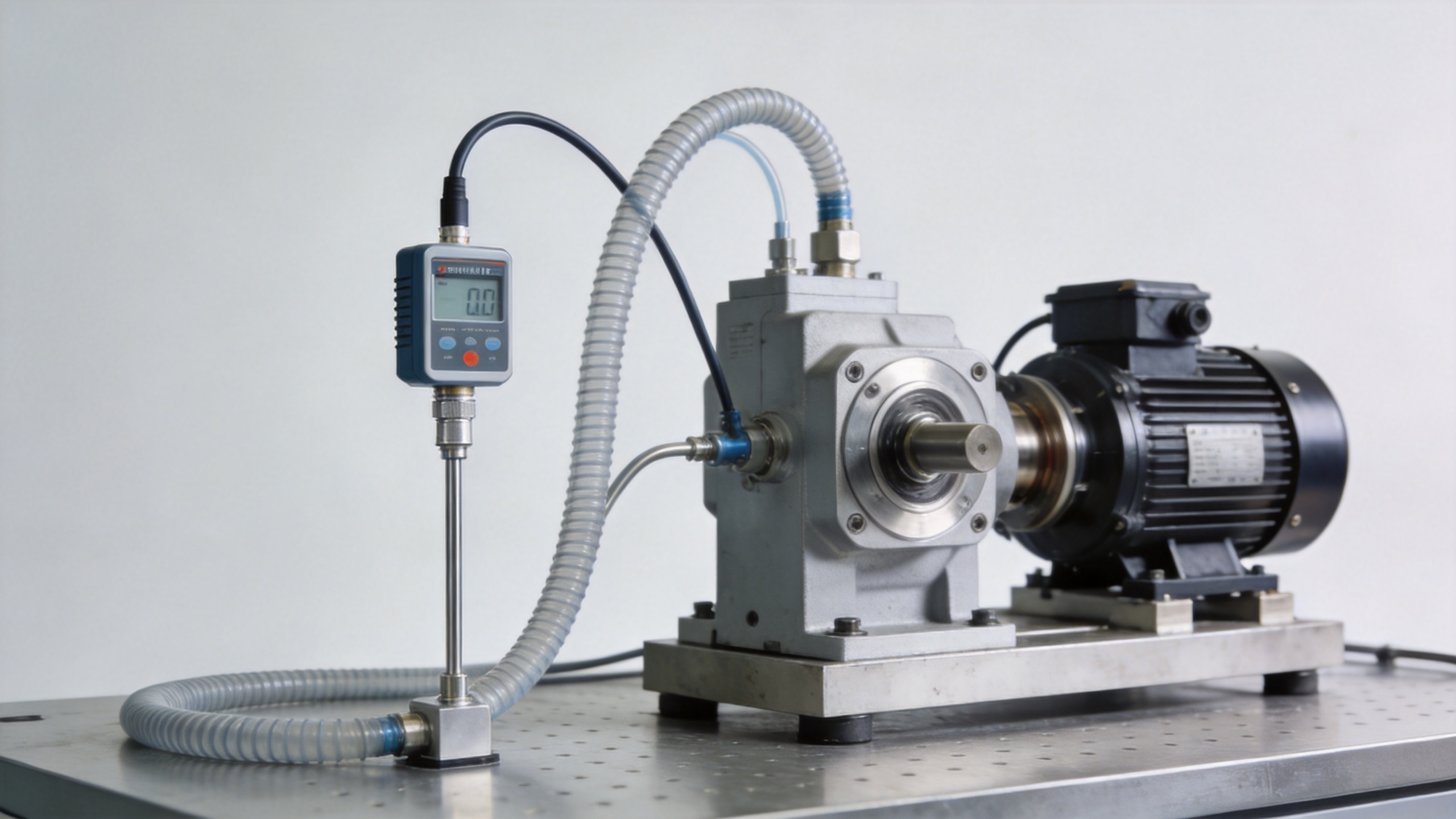
Control the loop, not just the chiller
The chiller is one component in a larger thermal system. Hose insulation, reservoir volume, fixture contact, bypass paths, sensor placement, and pump behavior can all influence the result. When temperature stability is poor, start by identifying which measured point moves first. A supply-temperature swing suggests a control or capacity issue. A stable supply with a drifting return may indicate a changing load, low flow, or altered heat transfer at the fixture.
For an industrial chiller supporting motor work, it is also useful to record supply and return temperatures together. Their difference is not a complete heat-balance calculation by itself, but it can show whether the loop is behaving consistently across repeated runs. Combine it with flow and test-load records before deciding that the motor is the source of a shift.
Settle time should be part of the procedure
A stable setpoint at the start of a run does not prove the entire rig is stable. Establish a pre-test stabilization period and define the evidence required before data collection begins. The requirement might include a controlled supply temperature, a repeatable return-temperature trend, a defined flow condition, and a fixed ambient measurement. Use the same criteria when a test is repeated.
After a load transition, allow the system to settle according to the method rather than choosing a convenient time. This is particularly important when a motor testing chiller is connected through a large fixture or long piping run. The thermal mass may smooth short disturbances, but it can also delay a meaningful change in the device under test.
Common sources of unstable test temperatures
- Heat load outside the planned envelope: A new duty cycle or higher torque can add heat faster than the loop was designed to remove it.
- Unverified flow at the fixture: A pump reading may not represent flow through the critical passage.
- Sensor placement mismatch: A sensor near the chiller outlet may not represent the motor contact-point temperature.
- Uninsulated or changing external conditions: Room airflow and exposed hose runs can influence low-delta-T tests.
- Control settings changed between runs: Different ramp or alarm settings make side-by-side comparisons harder to interpret.
- Incomplete event logging: Without synchronized load, flow, and temperature records, the cause of a drift may remain uncertain.
Addressing these points does not require claiming that any one motor testing chiller will fit every rig. It creates a documented path to evaluate whether the temperature-control system matches the test objective.
A practical acceptance checklist
Before relying on results from a new or modified loop, run a controlled verification sequence. Hold the test at representative low, nominal, and high-load stages. Record the supply and return temperature, flow indication, ambient condition, chiller operating state, and relevant motor temperatures. Then compare the traces against the tolerances written into the procedure.
- Confirm the temperature range, tolerance, and measurement locations.
- Simulate or run the expected load transitions.
- Document stabilization time before each measurement window.
- Check for repeatable response on a second run under the same conditions.
- Review alarms, interlocks, and data timestamps with the full test team.
This approach makes the motor testing chiller a transparent part of the evidence chain. It also helps procurement, test engineering, and controls teams discuss the same requirements: temperature range, dynamic heat load, fluid, flow, connection requirements, installation environment, and maintenance access.
Choose stability around the actual test conditions
The value of a motor testing chiller lies in making thermal conditions understandable and repeatable, not in quoting a generic capability. Define the control point, identify the changing load, verify the loop at the fixture, and record enough context to explain deviations. When those conditions are clear, an industrial chiller can be evaluated as a purposeful part of the motor-test system rather than a separate utility.
For a project-specific discussion, prepare the test temperature range, fluid, target flow, heat-load profile, fixture volume, electrical/control connection requirements, and ambient constraints. Those details allow the thermal-control approach to be assessed against the actual motor test rather than an assumed one.
 Hot News