
What Cooling Capacity Does a Semiconductor Chiller Need for Test Tools?
There is no defensible single kW number for a semiconductor chiller used with test tools. The right cooling capacity comes from the heat that reaches the coolant loop during the actual test sequence, not from the tester’s electrical nameplate alone. From an equipment-integration perspective, the first useful question is: what heat must the loop remove at the required supply temperature while the DUT, fixture, thermal head, and ambient conditions are all active?
A semiconductor chiller for an ATE handler, probe station, burn-in fixture, or thermal-stream interface should be selected against both a steady load and the highest credible transient. That distinction matters because a tool can look comfortable during idle operation yet exceed the available cooling capacity when a high-power device starts switching, a chamber ramps, or the fixture changes temperature.
Start With the Test Tool’s Real Thermal Duty
The thermal duty of a test setup is usually a stack of loads. Device dissipation is often the most visible term, but it is not the only one. A practical semiconductor chiller sizing sheet separates heat generated in the DUT, heat from sockets and interface electronics, thermal-head or platen losses, pump heat, and heat leak from hoses, manifolds, and the surrounding room.
- Steady-state DUT heat: the average heat released during the intended test pattern.
- Fixture and interface heat: load boards, socket hardware, contactors, power modules, or a thermal head that exchanges heat with the loop.
- Transient heat: pulses caused by power cycling, fast ramps, multisite testing, or a switch from one device state to another.
- Environmental heat gain: insulation losses, exposed metal, long hoses, and hot air around the equipment.
- Hydraulic overhead: pump heat and pressure-drop effects that can change the practical operating point.
With a precision chiller, it is tempting to begin with a model’s advertised capacity. A safer sequence is the reverse: define the duty first, then compare capacity at the required leaving-fluid temperature, flow, and ambient condition. Capacity at a mild catalog rating point may not represent capacity at a low test temperature or under a different coolant mixture.
Calculate the Cooling Load From Coolant Measurements
When the loop is operating, the most useful initial calculation uses coolant flow and the measured temperature rise across the tool:
Cooling load, Q = m-dot × Cp × ΔT
Here, m-dot is coolant mass flow, Cp is the coolant’s specific heat, and ΔT is return temperature minus supply temperature. The result is heat transferred to the fluid. For water near room temperature, Cp is often approximated as 4.18 kJ/kg·°C for a preliminary calculation; a glycol mixture requires its actual concentration- and temperature-dependent properties. This is a screening calculation, not a substitute for validating the complete test condition.
For example, suppose a loop moves 12 L/min of water and its return is 3°C warmer than its supply. The flow is about 0.2 kg/s, so the estimated load is 0.2 × 4.18 × 3 = 2.5 kW. If that reading reflects the highest sustained test state, the capacity selection must still account for uncertainty, transient peaks, heat leak, and the chiller’s capacity at the target supply temperature. It does not automatically mean a 2.5 kW unit is appropriate.
Apply Margin Without Treating It as a Guess
A temperature control chiller needs reserve capacity, but the margin should correspond to known uncertainty rather than a universal percentage. If the process heat is well measured and the duty cycle is stable, a modest engineering allowance may be sufficient. If power profiles, test temperatures, cooling-fluid concentration, or room conditions are still unknown, a wider allowance is reasonable until the tool can be characterized.
Instead of asking for “extra capacity,” ask what it protects against. It may cover a warmer lab, a future multisite fixture, a longer high-power dwell, an underestimated hose loss, or degradation in capacity at a lower setpoint. This approach makes the capacity discussion reviewable by the test engineer, facilities team, and equipment integrator.
Check Four Conditions Beyond kW
1. Supply temperature and stability
The semiconductor chiller must produce the desired supply condition at the required load, not simply reach that setpoint with little or no load. Stability requirements should be stated as a test requirement with the measurement location, sensor method, and allowed settling time. A tight number at the chiller outlet may not be the same as stability at the DUT interface.
2. Flow and pressure drop
A process chiller can have enough refrigeration capacity and still be a poor system match if flow is too low or the pump cannot overcome fixture, hose, and filter pressure drop. Obtain the required flow window, permissible pressure, coolant path restrictions, and connection details before approving a configuration.
3. Transient response
Test tools commonly change power faster than the refrigeration circuit can respond. Buffer volume, control logic, loop volume, and thermal mass can all affect the temperature excursion. For a semiconductor chiller, use a representative high-power sequence to evaluate overshoot, recovery time, and the return-temperature trend rather than relying only on an average load.
4. Coolant compatibility and condensation control
Fluid selection affects Cp, viscosity, pump demand, corrosion control, and capacity calculations. At low supply temperatures, insulation, vapor sealing, and dew-point management become system requirements. A precision chiller selection should therefore document the fluid, concentration, operating range, and condensation-control responsibility.
A Practical Sizing Workflow for Semiconductor Test
- List every cooled element and identify whether its heat is steady, cyclic, or transient.
- Record target supply temperature, allowable return temperature, required flow, coolant type, and expected room condition.
- Measure or estimate Q from flow, fluid properties, and supply-return ΔT during representative test states.
- Add a traceable allowance for uncertainty and future operating conditions.
- Compare the required capacity with the semiconductor chiller performance at the actual setpoint and ambient condition.
- Verify hydraulic performance, temperature stability at the interface, alarms, and recovery through a commissioning run.
The result should be a requirement such as “remove the confirmed peak thermal duty at the stated supply temperature and flow, with defined stability and recovery criteria,” rather than a bare capacity request. That wording helps a supplier assess a temperature control chiller against the whole duty cycle.
Questions to Resolve Before Final Selection
- What is the maximum sustained DUT and fixture heat during the intended program?
- What is the shortest, highest-power transient and how much temperature excursion is acceptable?
- Where are supply and return temperatures measured?
- What coolant, concentration, flow, and pressure-drop limits apply?
- Does the future test plan add sites, channels, or a lower operating temperature?
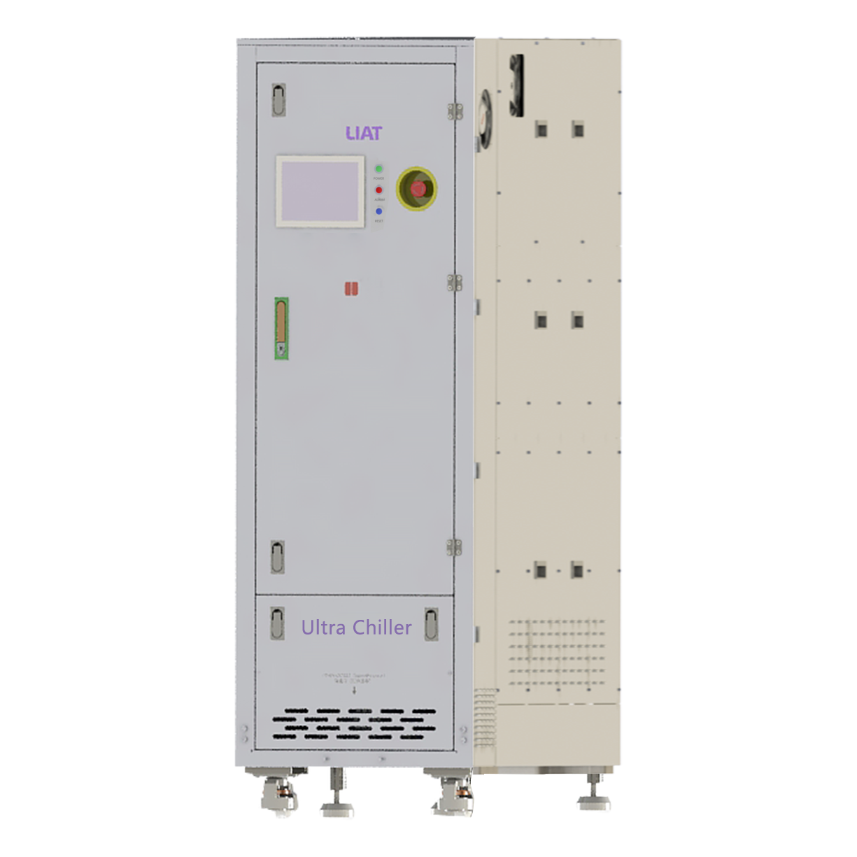
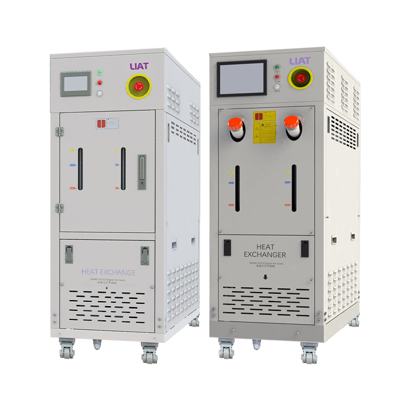
A properly sized semiconductor chiller is not simply the largest available unit. Oversizing can complicate control behavior and operating cost, while undersizing can cause temperature drift, slow recovery, and test interruptions. The better decision is a documented thermal balance, verified under a representative test sequence, then matched to a process chiller configuration with the required capacity, flow, control performance, and installation safeguards.
 Hot News