
How a Pipe Heater Jacket with PID Control Holds Exact Temperature
A heated line rarely behaves like a tabletop hot plate. Heat has to pass through the jacket, pipe wall, insulation, and process medium while ambient loss and changing flow conditions act in the other direction. A pipe heater jacket pid control system turns that moving thermal problem into a measured feedback loop. It does not make a pipe reach one universal temperature by itself; it continually compares a representative measured temperature with the setpoint and adjusts heater output as the process changes.
For process engineers, maintenance teams, and OEM designers, the useful question is not simply whether the controller has PID functions. It is whether the heater, sensor, power device, installation, and tuned control response work together. That distinction matters in applications where viscosity, crystallization risk, reaction stability, or transfer consistency depends on a stable line temperature.
What a PID-controlled heater jacket actually controls
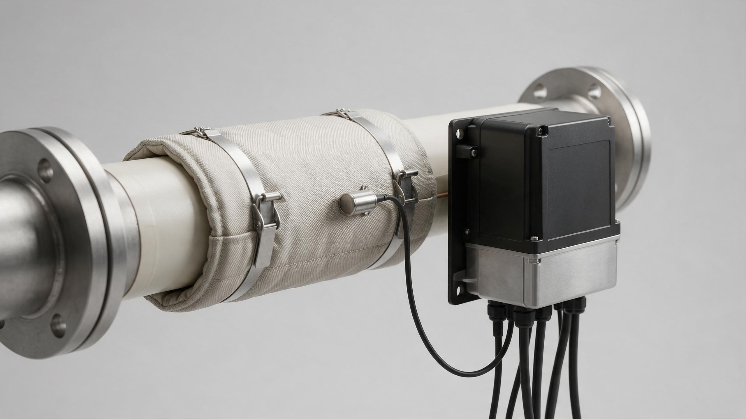
A typical pipe heater jacket pid control loop has five working parts: a flexible or fitted heating jacket, a temperature sensor, a PID controller, a switching device such as a properly selected SSR or contactor, and the pipe-and-product assembly being heated. The controller reads the sensor, compares that value with the target, and calls for more or less power. The heater jacket then adds energy around the pipe instead of concentrating heat at a small contact point.
The three PID terms answer different parts of the error signal. Proportional action responds to the current difference between measured temperature and setpoint. Integral action corrects a persistent offset that can remain when heat loss is steady. Derivative action reacts to the direction and rate of change, which can help moderate a response when the measured temperature is moving quickly. In real pipe heating, the useful settings depend on thermal mass, jacket coverage, insulation, flow, medium properties, and sensor location. They should be commissioned on the installed system rather than copied from another line.
Why the sensor position can decide the result
A controller can only correct the temperature it sees. If a sensor is mounted where it warms far earlier than the material of interest, the controller may reduce output before the process has received enough energy. If it is too far downstream or insulated from the pipe by a poor mounting method, the measured value may lag behind the actual heating event. In that case, power can remain on while the sensor still reports a low temperature, and the loop may overshoot after the heat has already reached the sensing point.
That is why a pipe heater jacket pid control design should define the controlled point before tuning begins. For a static or low-flow line, a well-coupled sensor near the critical pipe section may be appropriate. For flowing material, the controlled point may be selected around the process requirement rather than the physically hottest part of the jacket. The sensor must have good thermal contact, suitable protection for the environment, and routing that does not create misleading conduction paths.
How the jacket and the pipe create thermal lag
Thermal lag is not a controller fault. It is the time delay between an output change and the temperature change reported by the sensor. A thick-walled pipe, a heavy flange, a large product volume, wet insulation, high line speed, or a sensor positioned outside the heat path can all increase that delay. A heater jacket can distribute heat over a useful length of pipe, but it still has to heat the pipe wall before the process temperature changes.
During startup, a pipe heater jacket pid control loop may need different behavior from steady operation. A process with substantial thermal mass can tolerate a planned ramp or staged zone startup more gracefully than an immediate full-power demand. Once the line approaches its operating condition, PID values can be tuned for a measured response: how quickly the temperature approaches setpoint, whether it cycles, and how much it moves after a flow or ambient change. Autotune may provide a starting point, but the result still needs review under representative process conditions.
Use zones when one temperature is not representative
One sensor and one jacket circuit may be adequate for a short, uniform section. It becomes less representative when a line has long runs, major fittings, changing exposure, or separate heating duties. A flange or valve body can absorb heat differently from a straight pipe, while an exposed section can lose energy faster than an insulated section indoors.
Dividing the line into zones gives each section its own measured condition and output path. The goal is not to multiply controllers without reason; it is to avoid asking one sensor to represent a long and uneven thermal load. When zones are used, identify each sensor and heater circuit clearly, keep power capacity appropriate for each zone, and document the setpoint relationship between adjacent sections. This is particularly useful when the line connects to equipment with a different thermal profile, such as an industrial water chiller or a temperature-conditioned vessel.
Commissioning checks that produce usable control data
Before accepting a pipe heater jacket pid control installation, verify the mechanical and electrical details as carefully as the controller settings. A repeatable checkout can include:
- Confirm that the jacket fits the intended pipe section and that closures, leads, and insulation are installed as specified.
- Verify sensor type, polarity, input configuration, attachment method, and location against the control drawing.
- Check that the switching device, over-temperature protection, grounding, and supply circuit suit the heater load and local electrical requirements.
- Run the line through startup, steady operation, a representative flow change, and a planned shutdown while recording measured temperature and output behavior.
- Review whether a second independent temperature limit is required by the process hazard review.
These observations give a tuning discussion something concrete to use. A slow approach to setpoint may indicate limited heater capacity, excessive loss, or conservative settings. Repeated cycling can point to a sensor lag issue, overly aggressive proportional or integral action, or a mismatch between control cycle time and system response. The answer is usually found by examining the whole thermal path, not by changing one PID value repeatedly.
Specify the system around the process, not the controller label
When requesting a pipe heater jacket pid control solution, provide the pipe material and diameter, heated length, target temperature range, medium, expected flow changes, ambient conditions, insulation plan, available voltage, hazardous-area requirements where applicable, and desired sensor locations. Also state whether the objective is freeze protection, viscosity management, stable transfer temperature, warm-up, or a defined process hold. Those inputs allow the heating and control arrangement to be evaluated as one system.
PID control is valuable because it responds to measured error instead of treating the heater as a fixed-output device. Yet exact temperature performance is established by the full installation: heat transfer, sensor placement, controller configuration, safety limits, and commissioning evidence. With those pieces aligned, a pipe heater jacket can provide controlled, repeatable thermal conditions for an industrial line without relying on a vague claim of precision.
 Hot News